Transmission Line Summary
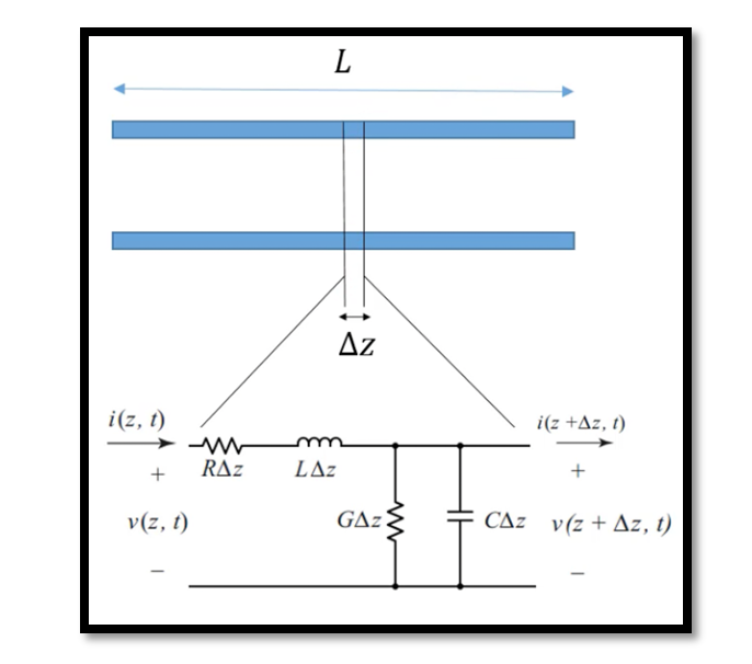
In transmission line analysis, the intricate interplay between voltage and current along its length necessitates a meticulous approach. Consider a transmission line with a length L and select a minute segment ΔZ for examination. This segment, owing to its diminutive size compared to the wavelength, can be aptly represented by a lumped network. Let’s delve into the mathematical underpinnings of this model.
Commencing from the left side of the circuit diagram, we encounter resistance and inductance. Notably, even slender wires exhibit inductance at high frequencies, obviating the need for elaborate spiral configurations. Following this, we encounter a conductance
G= 1/R and capacitance. The parameter RΔZ warrants our attention. Here, R signifies the series resistance per unit length for both conductors, expressed in Ω/m. To elucidate, let’s consider a practical scenario: R=100Ω/m. For our small section with L=1m and ΔZ=1mm, the resistance of this segment RΔZ computes to 0.1Ω.
Similar considerations apply to inductance, conductance, and capacitance. The top line exhibits resistance in series with inductance due to its inductive behavior at high frequencies. Additionally, there exists capacitance along with resistance between the plates, mirroring the physical reality of capacitive effects between two adjacent plates. This delineation of capacitance signifies the interaction between the top and bottom plates, embodying the essence of a capacitor. Thus, armed with this understanding, we embark on the analysis of our distributed network. By selecting infinitesimal segments and formulating pertinent equations, we lay the groundwork for our subsequent discourse.
While ΔZ tends towards zero due to its infinitesimal nature, our next endeavor involves delineating the equation formulations. In forthcoming articles, we shall elucidate the derivation process, culminating in the exposition of the general equation governing transmission lines.

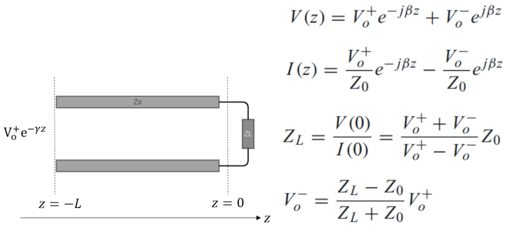
Consider a straightforward scenario of a transmission line terminated by a load. The transmission line comprises a pair of conductors separated by a dielectric material. At one terminus, it interfaces with a signal source, while at the other end, it connects to a load. Visualizing the setup, the transmission line is depicted with a signal source (symbolized by a voltage source) at one terminus and a load (represented by a resistor) at the opposite end. Herein, the signal source initiates an electrical signal propagation along the transmission line towards the load. This electrical signal, an alternating current (AC) of high frequency, traverses through the transmission line’s conductors.
At the load termination, the signal confronts the load impedance, herein manifested as a resistor. In the ideal scenario of impedance matching, the electrical signal seamlessly traverses the load sans significant reflection or distortion. The power delivered to the load hinges upon the voltage and current levels of the signal alongside the load impedance. However, a mismatch between the load impedance and the characteristic impedance of the transmission line triggers signal reflection back to the source. This phenomenon not only distorts the signal but also diminishes its strength. In severe instances, it can lead to electronic component damage.
Mitigating such adversities mandates meticulous attention to ensuring load impedance harmonizes with the characteristic impedance of the transmission line. This alignment, commonly referred to as impedance matching, is pivotal. Achieving impedance matching entails employing matching networks or impedance transformers capable of modifying either the load impedance or the transmission line’s impedance to achieve the requisite harmony. Through such measures, the deleterious effects of signal distortion and power loss due to impedance mismatch can be averted.
Let’s delve into the calculations for a transmission line terminated by a load, focusing on the impedance matching scenario.
Given Parameters:
Characteristic impedance of the transmission line: Z0
Load impedance: ZL
Reflection Coefficient (Γ): The reflection coefficient quantifies the portion of the signal reflected back from the load. It is given by the formula:

VSWR (Voltage Standing Wave Ratio): VSWR indicates how well the load impedance matches the transmission line’s characteristic impedance. It’s computed as:

Power Reflection Coefficient (ρ): The power reflection coefficient elucidates the proportion of incident power that gets reflected back from the load. It’s related to the reflection coefficient (Γ) by:

Example:
Suppose:
- Characteristic impedance of the transmission line, Z0=50Ω
- Load impedance, ZL=75Ω

Results:
- Reflection Coefficient (Γ): 0.2
- VSWR: 1.5
- Power Reflection Coefficient (ρ): 0.04
Conclusion:
In conclusion, the calculations and analyses presented underscore the critical importance of impedance matching in transmission line systems. By ensuring alignment between load and transmission line impedances, signal integrity is preserved, minimizing reflections and losses. Through the determination of parameters like the reflection coefficient and VSWR, engineers can gauge the effectiveness of impedance matching, thus optimizing system performance. As such, the pursuit of impedance matching stands as a cornerstone in the design and operation of transmission line systems, fostering reliable and efficient signal transmission in diverse electrical applications.


