Adjacent Channel Power in RF Signal Analysis
In the complex world of radio frequency (RF) communication, ensuring signal integrity and minimizing interference are paramount. One crucial metric that engineers and technicians rely on is Adjacent Channel Power (ACP). ACP, often referred to as the power level of the adjacent channel next to the fundamental channel, is a fundamental aspect of RF signal analysis, providing insights into the purity and efficiency of transmitted signals.
What is Adjacent Channel Power (dBm)?
Adjacent Channel Power, expressed in decibels relative to one milliwatt (dBm), represents the power level of the neighboring channel adjacent to the main or fundamental channel. In simpler terms, it measures the strength of signals bleeding into adjacent frequency bands. This measurement is essential in determining the potential for interference and the overall quality of the transmitted signal.


Absolute and Relative Measurement:
ACP can be evaluated in two ways: absolute and relative measurements. Absolute measurement refers to the direct power level of the adjacent channel, measured in dBm. It gives a clear indication of the interference level and is crucial in ensuring compliance with regulatory standards.
On the other hand, relative measurement, often denoted as dBc (decibels relative to the carrier), compares the power of the adjacent channel to the power of the main carrier signal. This measurement, known as Adjacent Channel Leakage Ratio (ACLR), provides a normalized view of interference, making it easier to compare across different systems and scenarios.

Importance of Accurate Measurement
Accurately measuring RF channel power is imperative for comprehensive signal analysis. Power density can vary significantly across different bandwidths, emphasizing the need for precision in measurement techniques. Engineers rely on sophisticated instruments and techniques to precisely capture ACP, ensuring optimal performance and compliance with regulatory standards.
Graphical Representation
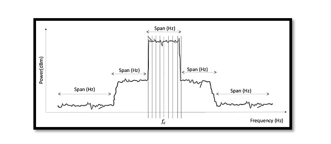
A graphical representation of power (dBm) against frequency (Hz) illustrates the power density variation across different bandwidths. This graph typically depicts spans for the lower and upper adjacent channels, providing a visual representation of signal purity and potential interference levels. Analyzing this graph enables engineers to fine-tune transmission parameters and mitigate interference effectively.

Power Density Variation:
The graph illustrates how power density varies across different bandwidths. Power density refers to the amount of power present per unit frequency. In an ideal scenario, the power would be concentrated within the main channel, representing the desired signal.
Spans for Lower and Upper Adjacent Channels:
Within the graph, spans for the lower and upper adjacent channels are typically delineated. These spans represent the frequency ranges adjacent to the fundamental channel. By examining the power levels within these spans, engineers can assess the magnitude of interference from adjacent channels.
Identifying Interference and Signal Purity:
Analysis of the graph enables engineers to identify interference sources and evaluate signal purity. Ideally, the power levels in the adjacent channels should be significantly lower than that of the fundamental channel. Any significant power present in the adjacent channels indicates potential interference, which could degrade signal quality.
Fine-Tuning Transmission Parameters:
By scrutinizing the graphical representation, engineers can make informed decisions to fine-tune transmission parameters. Adjustments such as bandwidth allocation, filtering techniques, and modulation schemes can be optimized to mitigate interference and improve signal purity.
Conclusion
A thorough understanding and accurate measurement of Adjacent Channel Power are indispensable. Whether optimizing signal purity, minimizing interference, or ensuring regulatory compliance, ACP serves as a cornerstone of RF transmission systems. By leveraging advanced measurement techniques, mathematical models, and graphical analysis, engineers can achieve optimal signal performance, enhance system reliability, and navigate the complexities of RF communication with confidence and precision.

Learn more about this topic by taking the complete course ‘Microwave Amplifier and Low Noise Amplifier (LNA) Design Theory and Principles online course – RAHRF526’. Watch the course videos for more detailed understanding. Also checkout other courses on RF system and IC design on https://rahsoft.com/courses/. Rahsoft also provides a certificate on Radio Frequency. All the courses offer step by step approach.
Tag:Adjacent Power, Power gain


