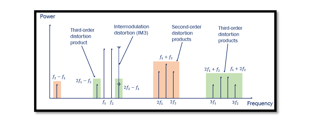
What is Third Order Intercept Point (IP3)?
The Third Order Intercept Point, or IP3, serves as a pivotal parameter characterizing the behavior of RF systems. At its core, IP3 delineates the point at which the third-order intermodulation distortion’s power (IMD3) coincides with the extrapolated linear output power of the desired signal. In simpler terms, it represents the threshold at which nonlinear effects start to significantly impact signal fidelity.
The Third Order Intercept Point (IP3) stands as a critical parameter in the realm of RF engineering, offering profound insights into the nonlinear behavior of devices operating in the radio frequency spectrum. At its essence, IP3 represents the point where the power of third-order intermodulation distortion (IMD3) intersects with the extrapolated linear output power of the desired signal. This intersection delineates the boundary between linear and nonlinear operation, serving as a fundamental reference point for characterizing the linearity and distortion characteristics of RF systems.
IP3, often referred to as TOI, plays a pivotal role in understanding the performance limitations and optimizing the design of RF devices. By quantifying the threshold at which nonlinear effects become significant, engineers can assess the device’s ability to faithfully reproduce input signals and minimize undesirable distortion products. In practical terms, achieving a higher IP3 translates to improved linearity, reduced distortion, and enhanced signal fidelity, crucial factors in applications ranging from wireless communications to radar systems.
Understanding Input and Output IP3
To comprehensively grasp IP3, it’s essential to differentiate between Input IP3 (IIP3) and Output IP3 (OIP3). IIP3 refers to the input power level to the Device Under Test (DUT) at the intercept point, whereas OIP3 denotes the output power level of the DUT at the same intercept point. Both IIP3 and OIP3 provide crucial insights into the behavior and performance of RF devices under varying input conditions.
Third Order Intermodulation Distortion (IMD3)
IMD3, the primary distortion mechanism at play concerning IP3, arises due to nonlinear effects and the mixing of signals within RF systems. Unlike other forms of distortion, third-order products generated by IMD3 are particularly problematic. While many unwanted products can be filtered out efficiently, third-order products pose a unique challenge. This is because they tend to cluster around the fundamental frequency, making filtration exceedingly difficult.
Implications and Applications
The significance of IP3 extends across a myriad of RF applications. In communications systems, understanding and optimizing IP3 is crucial for maintaining signal integrity, minimizing interference, and enhancing overall performance. Similarly, in RF amplifiers and transceivers, accurate characterization of IP3 facilitates the design of robust and efficient systems capable of meeting stringent specifications.

Graphical Representation of IP3
Visualizing the relationship between Input IP3 (IIP3) and Output IP3 (OIP3) can provide invaluable insights into the behavior of RF devices. The OIP3 can be calculated using the formula:
OIP3(dBm) = Gain(dB) + IIP3(dBm)
When plotted on a graph, with OIP3 on the y-axis and IIP3 on the x-axis, the resulting curve exhibits distinct characteristics. One key feature is the intersection point, representing the IP3 of the device. This intersection marks the boundary between linear and nonlinear operation, delineating the onset of significant intermodulation distortion.
Understanding the Graph
The graph of OIP3 against IIP3 typically reveals two distinct slopes. The first slope corresponds to the linear behavior of the fundamental frequency, where the output power increases linearly with the input power at a ratio of 1:1. This linear relationship signifies the ideal, distortion-free operation of the device.
However, as the input power continues to increase, the device eventually enters a nonlinear regime, characterized by the emergence of intermodulation distortion products. At this point, the slope corresponding to the third-order intermodulation products (IMD3) becomes steeper, with a ratio of 3:1 compared to the fundamental frequency.
Device Saturation and IP3
It’s important to note that the device typically saturates before reaching the IP3 point. Device saturation occurs when the device can no longer increase its output power linearly with the input power, leading to compression and distortion of the output signal.
The IP3 represents the theoretical limit of linearity, beyond which intermodulation distortion becomes predominant. While the device may not operate precisely at the IP3 due to practical limitations such as saturation, the IP3 serves as a crucial reference point for characterizing device performance and predicting its behavior under varying operating conditions.
Summary
The graph exhibits two distinct slopes representing the linear and nonlinear regions of operation. The slope corresponding to the fundamental frequency reflects a linear relationship between input and output power, typically at a ratio of 1:1. In contrast, the slope associated with the third-order intermodulation products (IMD3) is steeper, with a ratio of 3:1 compared to the fundamental frequency. This steepening slope underscores the increasing dominance of intermodulation distortion as the input power rises, ultimately culminating in the IP3 point. It’s essential to note that while the IP3 represents a theoretical limit of linearity, practical considerations such as device saturation often prevent devices from operating precisely at this point. Device saturation occurs when the device’s output power reaches its maximum limit, leading to compression and distortion of the output signal. Despite this limitation, IP3 remains a vital metric for assessing device performance, guiding design decisions, and optimizing system architectures for enhanced linearity and signal integrity.

Learn more about this topic by taking the complete course ‘Microwave Amplifier and Low Noise Amplifier (LNA) Design Theory and Principles online course – RAHRF526’. Watch the course videos for more detailed understanding. Also checkout other courses on RF system and IC design on https://rahsoft.com/courses/. Rahsoft also provides a certificate on Radio Frequency. All the courses offer step by step approach.


