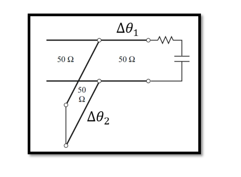
Microstrip Line Dimensions: Calculation Example
Microstrip lines stand as the backbone of modern high-frequency circuit design, offering a blend of performance and convenience. Yet, determining their precise dimensions can be akin to solving a puzzle. In this blog post, we’ll embark on a journey through a calculation example, shedding light on how to decipher the dimensions needed for microstrip lines, especially when armed with information from the Smith chart during the matching process.
Understanding Microstrip Lines
Before delving into the calculations, let’s establish a foundational understanding of microstrip lines. These transmission lines consist of a conductive trace patterned atop a dielectric substrate, often with a ground plane beneath. This configuration enables the propagation of electromagnetic signals at microwave frequencies, crucial for diverse applications from antennas to microwave integrated circuits.
Deciphering Dimensions: A Step-by-Step Guide
Step 1: Obtaining Electrical Length from the Smith Chart
In our scenario, we’re already armed with the electrical length (β⋅l) gleaned from the Smith chart during the matching process. This electrical length represents the phase shift introduced by the microstrip line at the desired frequency.
Step 2: Calculating Change in Phase (Δθ)
We utilize the relationship between electrical length (β⋅l) and change in phase (Δθ), which is given by:
Δθ=−2⋅β⋅l
Here, β represents the propagation constant, and l denotes the physical length of the microstrip line.
Step 3: Interpretation of Δθ
The change in phase (Δθ) corresponds to the angle of the reflection coefficient (ΓΓ) on the Smith chart. It signifies how much the signal’s phase is altered upon reflection at the load impedance.
Step 4: Further Analysis and Design Considerations
With the change in phase (Δθ) determined, we can delve into further analysis and design considerations. This involves leveraging this information to refine the microstrip line’s dimensions, ensuring optimal performance, impedance matching, and signal integrity.
Example Application:
Let’s illustrate these concepts with a practical example:
- Electrical length (β⋅l) obtained from Smith chart: 120∘
- Change in phase (Δθ): −240∘ (Derived from Δθ=−2⋅β⋅l)
Determining the dimensions of a microstrip line using the given electrical length (βL) and propagation constant (β).
Step 1: Given Parameters
- Electrical length (βL):90∘
- Propagation constant (β): Assume a value based on the dielectric material and substrate dimensions.
Step 2: Calculate the Physical Length (L)
Using the formula:
L=βL/β
Given that βL=90∘ and assuming β=2π/λ (where λ is the wavelength in the substrate), let’s assume a specific value for β based on the substrate and frequency of operation. For example, if we assume β=10rad/m, then:
L= 90∘/10rad/m =9m
Step 3: Design Considerations
With the physical length (L) determined, you can proceed to design the microstrip line layout. This involves selecting the substrate material, determining the trace width, and considering impedance matching requirements to achieve the desired characteristic impedance and performance specifications.
Example Calculation Summary:
- Electrical length (βL): 90∘
- Propagation constant (β): Assumed value (e.g., 10 rad/m10rad/m)
- Physical length (L): 9m
Conclusion:
Mastering the art of microstrip line dimension determination empowers engineers to craft high-performance circuits tailored to specific requirements. By leveraging insights from the Smith chart and understanding the relationship between electrical length, change in phase, and microstrip line dimensions, designers can navigate the intricacies of microwave circuitry with confidence. In essence, unraveling the dimensions of microstrip lines is not merely about calculations but a journey of understanding the intricate dance of electromagnetic waves on the substrate—a journey that paves the way for innovation and breakthroughs in high-frequency circuit design.

Learn more about this topic by taking the complete course ‘Microwave Amplifier and Low Noise Amplifier (LNA) Design Theory and Principles online course – RAHRF526’. Watch the course videos for more detailed understanding. Also checkout other courses on RF system and IC design on https://rahsoft.com/courses/. Rahsoft also provides a certificate on Radio Frequency. All the courses offer step by step approach.


