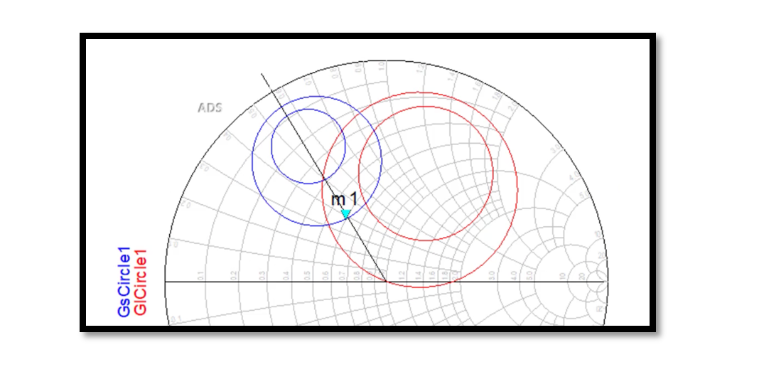
Understanding Circles of Constant Noise Figure
In the low noise amplifier (LNA) design, one of the critical metrics engineers grapple with is noise figure (NF). NF quantifies how much a device degrades the signal-to-noise ratio, crucial in applications where signal fidelity is paramount. Circles of Constant Noise Figure, an indispensable concept in LNA design, offer a roadmap for achieving optimal performance. Let’s delve into this intricate yet essential aspect of amplifier design.
Understanding the Noise Figure Formula
The noise figure (F) of an amplifier is determined by a combination of intrinsic device properties and external factors. For a given transistor, the noise figure can be expressed as:

Where:
- Fmin represents the minimum noise figure of the transistor, achieved when the source admittance (Ys) matches the optimum source admittance (Yopt).
- RN is the equivalent noise resistance of the transistor.
- Gs is the real part of the source admittance.
- Minimum Noise Figure (Fmin): This is the lowest attainable noise figure for a given transistor. It occurs when the source admittance matches the optimum value, indicating ideal matching conditions.
- Equivalent Noise Resistance (RN): Characterizing the internal noise behavior of the transistor, RN encapsulates the noise generated within the device.
- Real Part of Source Admittance (Gs): Reflects the conductive properties of the source presented to the transistor.
Constant Noise Figure (NF) circles represent regions in the complex admittance plane where the noise figure remains constant for a given amplifier configuration. These circles are instrumental in navigating LNA design, offering insights into achievable performance under varying source conditions.
Equation of Constant NF Circles
The equation governing the NF circles is:

- ∣Ys−Yopt∣2: This term represents the squared magnitude of the difference between the source admittance (Ys) and the optimum source admittance (Yopt). It quantifies the deviation from ideal matching conditions.
- Gs: The real part of the source admittance, indicating the conductive properties of the source.
- RN: The equivalent noise resistance of the transistor, characterizing its internal noise behavior.
- F: The desired noise figure for the amplifier configuration.
- Fmin: The minimum noise figure achievable for the transistor.
- F−Fmin: This term represents the deviation of the desired noise figure (F) from the minimum achievable noise figure (Fmin). It reflects how far the desired noise figure is from the best achievable noise performance.
- RN/Gs: This fraction determines the scaling factor for the deviation in noise figure. It’s the ratio of the real part of the source admittance (Gs) to the equivalent noise resistance (RN). Essentially, it governs how much the noise figure deviation influences the size and shape of the constant NF circles.
- The product of RN/Gs and F−Fmin represents the amount by which the deviation in noise figure influences the squared magnitude of the difference between the source admittance and the optimum source admittance. This product essentially sets the radius and orientation of the constant NF circles in the complex admittance plane.
Conclusion
In summary, the equation of constant NF circles relates the deviation in noise figure to the distance between the source admittance and the optimum source admittance. It’s a powerful tool for understanding and optimizing LNA performance under varying source conditions.

Learn more about this topic by taking the complete course ‘Microwave Amplifier and Low Noise Amplifier (LNA) Design Theory and Principles online course – RAHRF526’. Watch the course videos for more detailed understanding. Also checkout other courses on RF system and IC design on https://rahsoft.com/courses/. Rahsoft also provides a certificate on Radio Frequency. All the courses offer step by step approach.


