Stability Example Using ADS
Importance of Stability:
Stability is crucial in LNA design because it directly impacts the amplifier’s performance and reliability. Instability can lead to oscillations, which not only distort the signal but also cause potential damage to the amplifier and other components in the system. Therefore, ensuring stability is essential for achieving consistent and high-quality signal amplification.
Stability Criteria:
Stability criteria define the conditions under which an amplifier remains stable. Unconditional stability implies that the amplifier is stable under all passive source and load impedances. Conditional stability means the amplifier is stable only within a certain range of impedances, while potentially unstable conditions indicate that instability may occur under specific circumstances.
Stability Circles and Smith Chart:
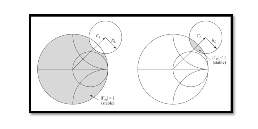
Stability circles are graphical representations of stability conditions on the Smith chart. These circles provide a visual indication of the regions where the amplifier remains stable. By plotting stability circles, designers can easily identify stable operating points and optimize amplifier performance accordingly.
Derivation of Stability Circle Equation:
The stability circle equation is derived from the scattering parameters of the amplifier. It represents the condition for stability in terms of the input and output reflection coefficients and the S-parameters. Understanding the derivation of this equation helps designers grasp the mathematical principles underlying stability analysis.
Design Considerations for Stability:
Designing stable LNAs requires careful consideration of factors such as matching networks, biasing schemes, and component selection. Proper impedance matching between the amplifier and its surrounding circuitry is essential for maximizing power transfer and minimizing reflections, thereby improving stability.
Future Trends and Challenges:
Conclude by discussing emerging trends and challenges in LNA design related to stability, such as miniaturization, integration, and operating at higher frequencies. Encourage readers to stay updated on advancements in stability analysis techniques and design methodologies.
By incorporating these detailed insights into your blog, readers can gain a thorough understanding of stability in LNA design and its significance in ensuring reliable and high-performance microwave amplifiers.
Here’s a stability example question inspired by microwave engineering principles as outlined in textbooks like “Microwave Engineering” by David Pozar:
Stability Analysis of a Microwave Amplifier
Consider a microwave amplifier designed for a satellite communication system operating at 5 GHz. The amplifier utilizes a GaAs field-effect transistor (FET) as its active device. The S-parameters for the FET are provided as follows:
S11=0.3+j0.2
S12=0.1+j0.05
S21=0.15+j0.3
S22=0.25+j0.15
- Calculate the stability circles for both the input and output sides of the amplifier.
- Plot the stability circles on the Smith chart and identify the stable regions.
- Determine if the amplifier is unconditionally stable, conditionally stable, or potentially unstable.
- If the amplifier is potentially unstable, propose design modifications to improve stability while maintaining desired performance metrics such as gain and noise figure.
Provide a detailed analysis explaining the stability assessment and any design recommendations.
This example question challenges to apply stability analysis techniques to evaluate the stability of a microwave amplifier and propose design modifications if necessary. It tests their understanding of stability criteria, S-parameter analysis, and practical implications in amplifier design.

Here’s a step-by-step guide on how to demonstrate stability analysis using Keysight Advanced Design System (ADS), a popular RF and microwave design software:
Step 1: Setup the Circuit
- Launch ADS and create a new workspace.
- Select “Schematic” to open the schematic design environment.
- Design your LNA circuit using the appropriate components (e.g., transistors, resistors, capacitors).
- Ensure that the LNA circuit includes matching networks at the input and output ports to achieve proper impedance matching.
Step 2: Perform S-parameter Simulation
- Once the LNA circuit is designed, you need to simulate its S-parameters.
- Go to the “Simulation” menu and select “Linear/Time Domain Simulation” > “S-Parameter.”
- Set the frequency range and other simulation parameters as needed.
- Run the simulation to obtain the S-parameter data for the LNA circuit.
Step 3: Plot Stability Circles
- After obtaining the S-parameter data, you can plot stability circles on the Smith chart.
- Go to the “Graph” menu and select “Smith Chart” to open a Smith chart window.
- Click on the “Data Display” button and choose “Add Data” to import the S-parameter data.
- Select the S-parameter data file (Touchstone file) generated from the simulation.
- Once the data is loaded, right-click on the Smith chart and choose “Add Stability Circles” from the context menu.
- Adjust the stability circle parameters (e.g., center frequency, radius) based on your design specifications.
- The stability circles will be plotted on the Smith chart, indicating the regions of stability for the LNA circuit.
Step 4: Analyze Stability
- Examine the stability circles on the Smith chart to determine the stability of the LNA circuit.
- Check if the stability circles intersect the unit circle (indicating potential instability) or remain entirely within the unit circle (indicating stability).
- Evaluate the stability under different load conditions by adjusting the load impedance and observing changes in the stability circles.
- Identify any potential instability regions and consider design modifications (e.g., adjusting biasing, optimizing matching networks) to improve stability while meeting performance requirements.
Step 5: Optimization and Verification
- Iterate the design process as needed to optimize stability while maintaining desired performance metrics.
- Use ADS’s optimization tools to automatically adjust circuit parameters and achieve desired stability margins.
- Verify the stability analysis results through further simulations and measurements, ensuring that the LNA circuit operates reliably under various conditions.
By following these steps, you can effectively demonstrate stability analysis for an LNA circuit using ADS, enabling you to optimize the design for robust and high-performance operation in microwave applications.

Learn more about this topic by taking the complete course ‘Microwave Amplifier and Low Noise Amplifier (LNA) Design Theory and Principles online course – RAHRF526’. Watch the course videos for more detailed understanding. Also checkout other courses on RF system and IC design on https://rahsoft.com/courses/. Rahsoft also provides a certificate on Radio Frequency. All the courses offer step by step approach.


