Introduction to Microstrip Lines: Fundamentals and Construction
Introduction
In the world of high-frequency circuits, microstrip lines stand as an integral element. These structures, consisting of a conductor on a dielectric substrate, play a pivotal role in modern electronic systems. Understanding their design, characteristics, and how to calculate their characteristic impedance is fundamental for engineers and enthusiasts alike.
Anatomy of Microstrip Lines
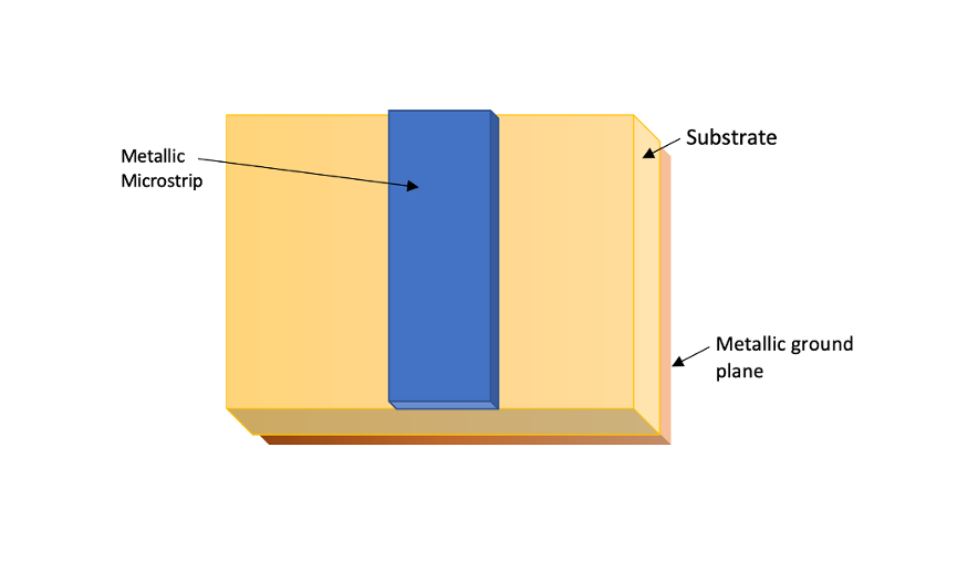
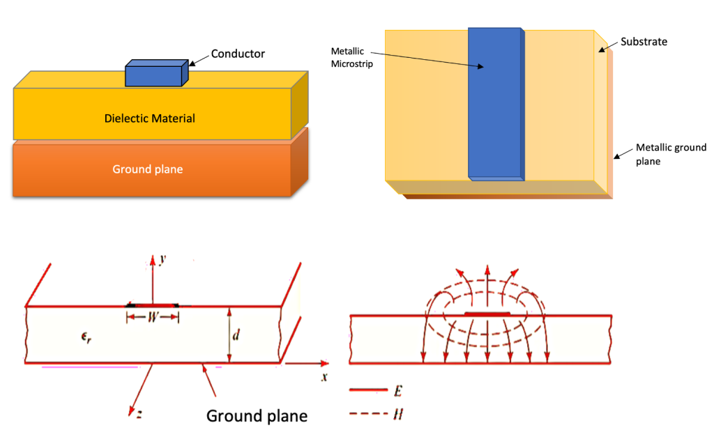
At the heart of a microstrip line lies a thin strip of conductor positioned atop a dielectric material, which is in turn placed over a ground plane. The conductor typically comprises copper due to its excellent conductivity and affordability. This metallic strip acts as the signal trace, guiding electrical signals through the circuit. The dielectric material, often made of materials like FR-4, PTFE, or ceramic, determines the speed at which signals travel within the microstrip line. This parameter, known as the dielectric constant (εr), influences the characteristic impedance and overall performance of the line.
Adjacent to the dielectric material lies the ground plane, usually a conductive layer beneath the dielectric. This serves as a return path for the electrical signals, maintaining signal integrity and reducing electromagnetic interference.

Calculating Characteristic Impedance
The characteristic impedance (Z0) of a microstrip line is crucial in designing high-frequency circuits. Given the dimensions of the line, it can be calculated using empirical formulas, such as: For Microstrip with Finite Substrate Thickness:

For Microstrip with Infinite Substrate Thickness (Approximation):

Understanding these equations is crucial, as they allow engineers to tailor microstrip designs for specific impedance requirements, ensuring optimal signal transmission.
Design Considerations and Applications
Microstrip lines find extensive application in high-frequency circuits, including microwave circuits, antennas, and RF modules. Microstrip line stands out as one of the most popular types of planar transmission lines due to its versatility. It can be fabricated through photolithographic processes, allowing for precise manufacturing in integrated circuits. Its ease of miniaturization and integration with both passive and active microwave devices makes it a preferred choice among engineers and designers working on compact, high-performance systems.
Moreover, it constitutes a simple transmission line with phase velocity vp=c and propagation constant β=k0, which is integral in determining the behavior and characteristics of the signals traveling through it. This simplicity in understanding its fundamental parameters further contributes to its widespread adoption and utilization in various electronic applications.
Furthermore, Antennas, pivotal components in RF systems, heavily rely on microstrip lines for their exceptional performance. These lines are intricately woven into antenna designs, shaping the radiation patterns and optimizing antenna efficiency. From mobile devices to complex radar systems, microstrip-based antennas facilitate wireless connectivity, navigation, and surveillance with unparalleled precision and reliability.
RF modules, essential building blocks in wireless technology, harness microstrip lines to weave intricate networks within compact spaces. These modules, integrated into smartphones, IoT devices, and wireless sensors, rely on microstrip lines to transmit and receive data efficiently. Their ability to seamlessly integrate with both passive and active microwave components empowers these modules to function flawlessly in diverse environmental conditions, from urban landscapes to remote and challenging terrains. Beyond their direct application in specific devices, microstrip lines play a crucial role in RF system integration. Their compatibility with modern fabrication techniques allows engineers to seamlessly integrate them into complex circuit layouts. This integration is pivotal in achieving optimized performance, reducing signal losses, and enhancing the overall reliability of high-frequency systems.
Key Equations and Calculations for Microstrip Line Design
Microstrip lines are a critical component in high-frequency circuit design and have various equations and calculations associated with their parameters and performance. Here are some equations and calculations related to microstrip lines: Characteristic Impedance (Z0) Calculation: The characteristic impedance of a microstrip line can be calculated using various empirical formulas. One common formula for the characteristic impedance of a microstrip line on a substrate with relative permittivity εr, strip width W, and substrate thickness h is the closed-form equation proposed by Hammerstad and Jensen:

Effective Dielectric Constant (εeff) Calculation: The effective dielectric constant considers the fringing fields and can be calculated using the following equation:

Phase Velocity Calculation: The phase velocity of a signal traveling through a microstrip line is given by: Where c = Speed of light in a vacuum

Capacitance per Unit Length Calculation: The capacitance per unit length (C) of a microstrip line can be computed as: Where ε0 = Permittivity of free space

Inductance per Unit Length Calculation: The inductance per unit length (L) of a microstrip line can be approximated as: Where μ0 = Permeability of free space

These equations provide insights into the behavior and characteristics of microstrip lines, aiding in their design and optimization for specific applications. Experimental validation or electromagnetic simulation tools are often used to refine and verify these calculations.
Conclusion: Microstrip lines represent a cornerstone in the realm of high-frequency circuits. Their simple yet powerful design, comprising a conductor, dielectric substrate, and ground plane, facilitates efficient signal transmission. Understanding how to calculate their characteristic impedance empowers engineers to fine-tune these structures for optimal performance, enabling the creation of high-performance electronic systems in various applications.

Learn more about this topic by taking the complete course ‘RF Microwave and Radio Frequency Transmission Theory Online Course – RAHRF200’. Watch the course videos for more detailed understanding. Also checkout other courses on RF system and IC design on https://rahsoft.com/courses/. Rahsoft also provides a certificate on Radio Frequency. All the courses offer step by step approach.


