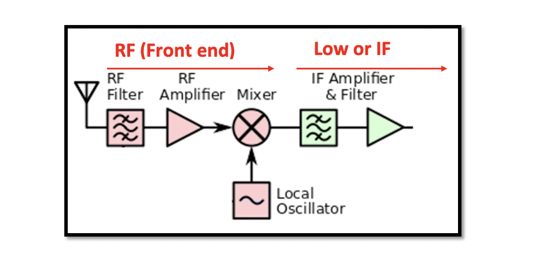
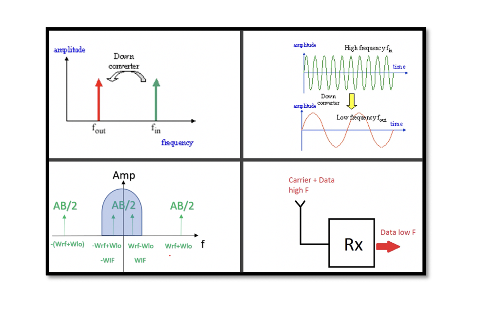
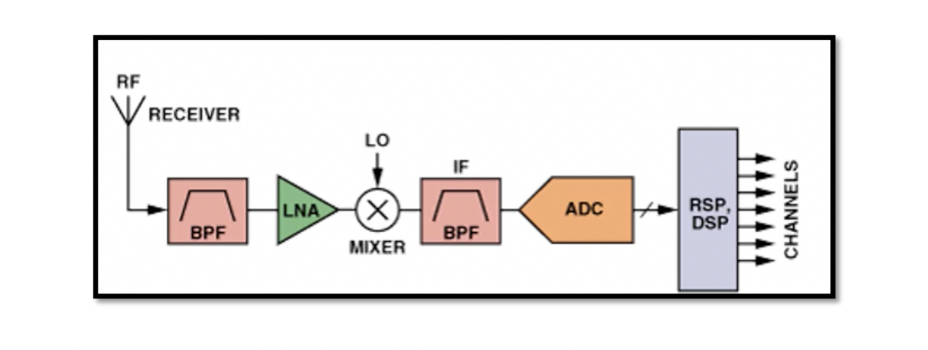
Heterodyne Receiver In a heterodyne receiver the received signal from an antenna is down converted from RF signal to intermediate frequency. Win is not equal to WLO. The basic structure of heterodyne receiver is shown below. There is an antenna …
Down Conversion Down conversion occurs in the receiver. Before transmitting the data, it is shifted to high frequency and is captured by the antenna and passed on to the receiver. The captured signal is then shifted from high frequency to …
An RF module is a block that has sub-blocks inside it. It is a small electronic circuit used to transmit and receive radio waves on one of a number of carrier frequencies. These carrier waves have high frequencies. RF module …
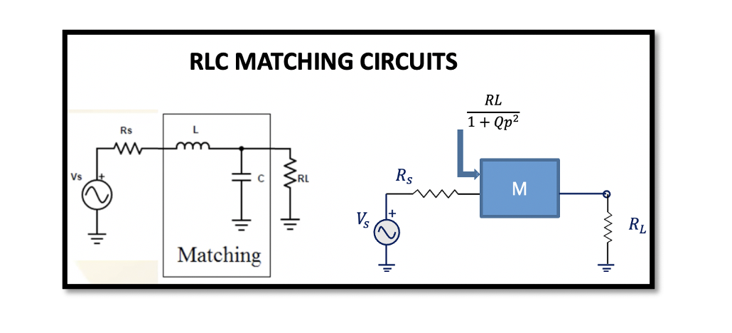
Why matching circuits are needed? As we know that in RF systems maximum power delivery is the main objective while designing a circuit and to maximise the power delivery with minimum loss, matching networks are created. Read understanding the need …
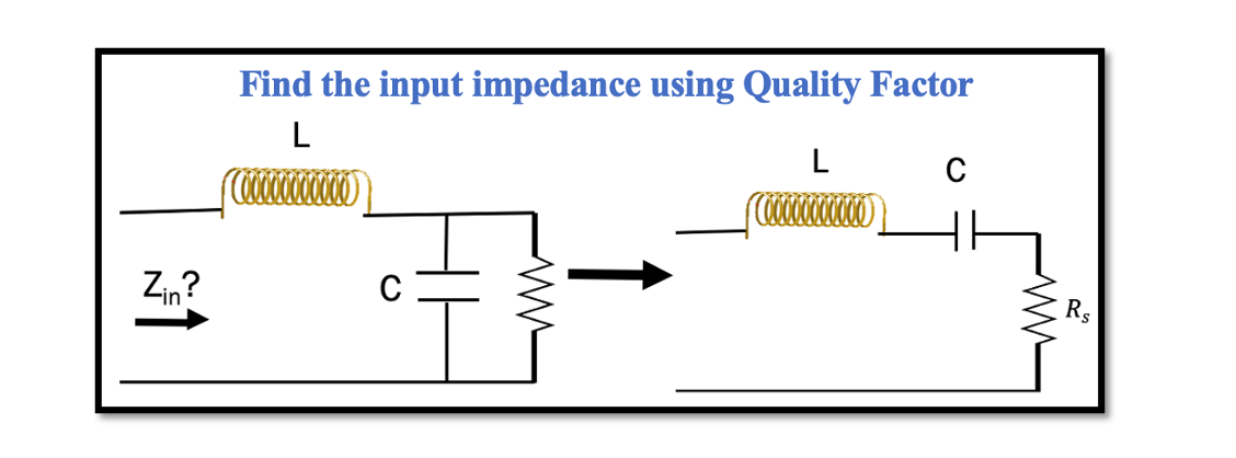
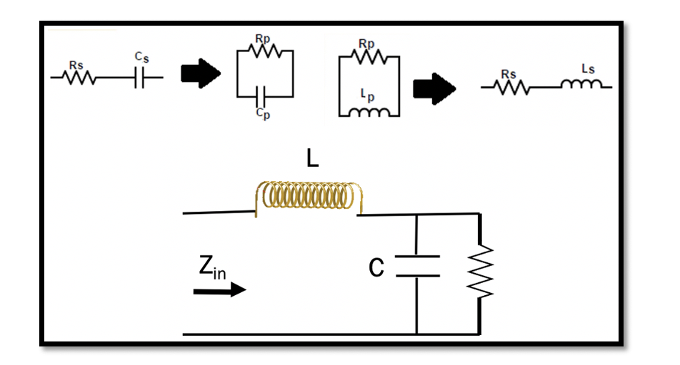
In the previous section, Resonance and Quality Factor we discussed the method 1 for series to parallel conversion and vice versa using Quality factor. To give a summary of method 1, this method is a process of conversion of series …
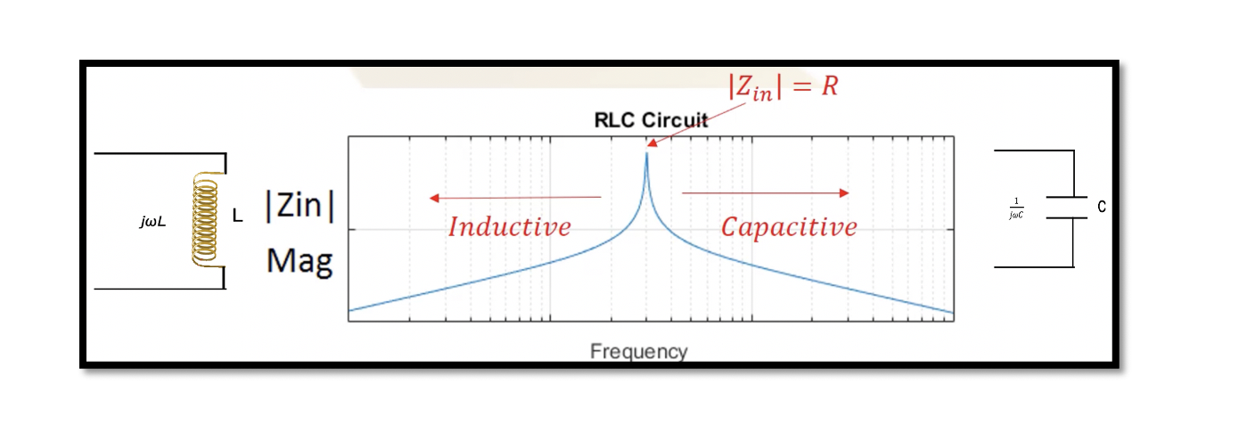
Resonance: Resonance in a RLC circuit is when we cancel out all the reactants in the circuit. In RLC circuit L & C are the reactants. So the reactances of inductance and capacitance are essentially cancelled out, and only resistance …
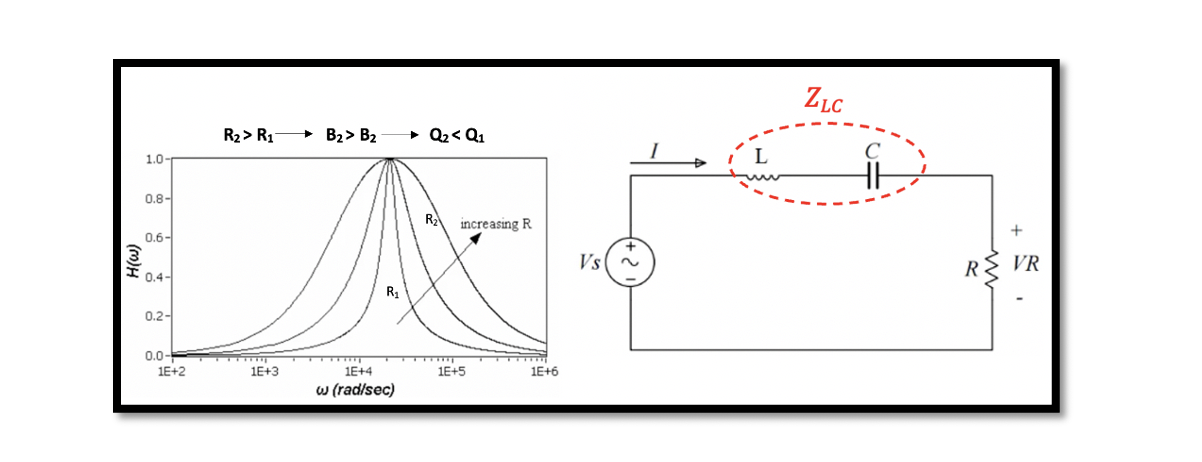
Defining the Transfer function for series RLC circuits Transfer function {H(w)} is equal to output voltage Vout divided by input voltage Vin which can be further written as: The graph represents the magnitude versus frequency. There are three different transfer …
In radio frequency systems, passive networks and passive circuits are used to match or transform impedance. Passive networks are also used to tune the RF blocks, obtain desired input and output impedance, and design different filters. Therefore, it is important …
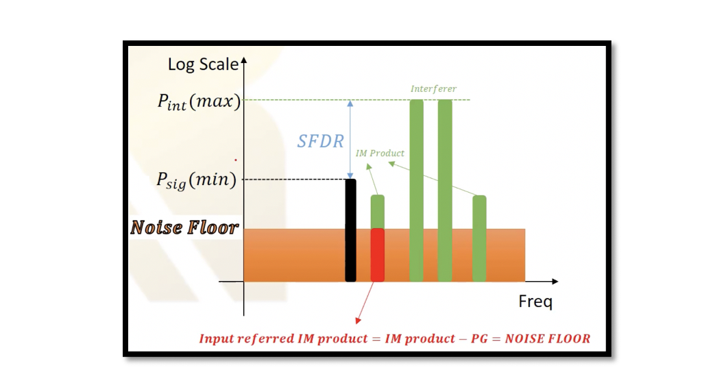
What is Dynamic Range? Dynamic range is the maximum input level that a receiver can tolerate divided by the minimum input level signal, which is defined as sensitivity. Dynamic range is equal to a maximum power of signal over minimum …
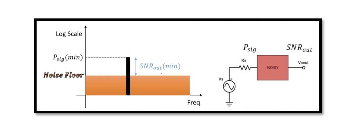
What is Radio Sensitivity? Sensitivity is the minimum signal which can be detected with accepted output SNR (Signal to Noise Ratio). Accepted output SNR is sometimes called as the minimum output SNR (SNRo, min). It means we are not allowed …

