Maximum Power Transfer in RF Circuits
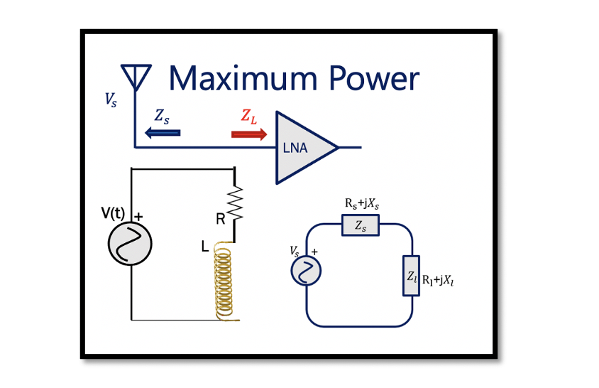
Maximum power is an important feature in RF systems. The main objective while designing a RF circuit is to have maximum power transfer with minimum loss to avoid wasted power. For example, while designing an antenna the aim is to have maximum power transfer from antenna to the Low Noise Amplifier (LNA). Here we are trying to transfer as much power as we can to reduce the loss.
We have a circuit as shown below, transferring the maximum power from source to load:

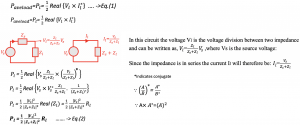
Vl is the voltage of the load and Il is the current which is through the load. Here, Il* represents the conjugate of current. Read about complex power and conjugate.
The circuit has two parts source and load, where Zl is the load impedance. The Vs is the power source and Zs is the output impedance of the source or called as the generator. As discussed previously how power is represented as complex number, here the source impedance is the combination of real and imaginary values (Rs + jXs). Rs is the real part and jXs is the imaginary part. The load and source has complex values represented as “RL + jXL” & “Rs + jXs”. Here the imaginary parts (jXL & jXs) can be either positive or negative depending on the non-linear devices, like for inductance it is positive and for capacitance it is negative.

Using equation (2) to find the maximum power transfer in the circuit by substituting the values of Zs and Zl we get:
To have maximum power transfer in this circuit the source voltage Vs should be high. The source voltage Vs cannot be changed, however, to have maximum power transfer we can input jXl = -jXs, it means Zl = Zs* = Rs – jXs, so the imaginary parts cancel outs, hence we get the maximum power. By doing this we are trying to equalize the real part of the load to the real part of the source and making the imaginary part equal to negative of the imaginary part of the source. When we say Zl = Zs* we are doing the conjugate as shown below:
The maximum power is the available power (Pavl=Pmax) of the source that can be delivered to the load. It is the largest amount of power and is dependent on the source parameters Vs & Rs, provided Zl = Zs*. If the load impedance Zl is not equal to complex conjugate of the source impedance Zs* then power Pl < Pavl (Pmax) which is not the ideal case. Here, we need Pl = Pavl for maximum power transfer.
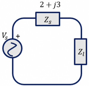
Example: Choose Zl for maximum power where Vs = 4 cos (wt)

Making the load impedance Zl equal to complex conjugate of the source impedance Zs* we get: Zl = Zs* = 2-j3
We know that Z= R+jX, so Rs = 2, Now, using equation (3) we calculate the maximum power transfer for this circuit.
Vs = 4 cos (wt), Rs = 2

Hence, the maximum power transfer calculated for this circuit is 1W.


