Drawbacks of Non-linear System: Gain Compression
Gain compression is the most important problem that is faced in a non-linear system. Read about the effects of Non-Linearity in RF systems. Harmonic distortion is one of the drawbacks of having a non-linear system that is discussed in the previous section, harmonic distortion.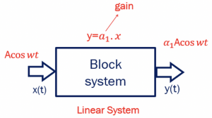
If we have a linear system with input x(t)=Acos wt, then we will have y=a1.x, where ‘a’ is the gain, so the output for this linear system would be a1Acos wt. In the non-linear system, the output would be y(t)=a1.x +a2.x2+a3.x3, and we can find the gain for this system by defining the gain. We have different kinds of amplitudes in a non-linear system as it produces harmonics. So gain can be defined here as the output amplitude A0 of the fundamental frequency by the input amplitude ‘ A.’ Using the equations for input and output, we could find out the gain in the system. The output equation can be further written as:![]()
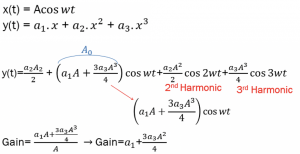
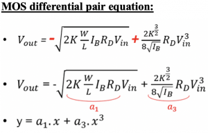
In a non-linear system, we have a1.x, a2.x2 & a3.x3, where most of the systems, the a1 and a3, have opposite signs. If a1 is positive, then a3 will be negative. This is true for most differential systems. In the section effects of Non-Linearity in RF systems, we showed that in the MOS differential pair, the equation for Vout with a1 and a3 have opposite signs, and there is no a2.
When the system is linear, the gain is constant, but in a non-linear system, gain depends on input amplitude. So, assuming a1 is positive and a3 is negative, we can write the gain as:
As we increase, the amplitude gain will decrease as a3 is negative. So when the system is linear, the gain is a1, which is constant; in a non-linear system, our gain will change and depend on amplitude ‘A.’
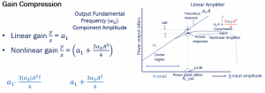
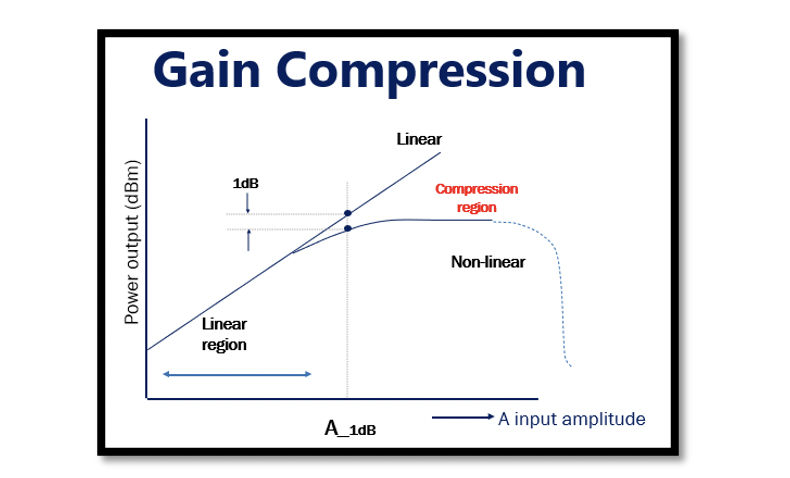
This example graph shows a theoretical comparison between a linear and non-linear amplifier to explain gain compression. The graph shows a region called a linear region. The input amplitude in this region is small; therefore, the part (3a3A2/4) in the equation can be neglected. In the linear region, the gain for both linear and non-linear amplifiers remains the same. In a linear amplifier, the gain is constant, and when the input amplitude increases, the output increases at the same rate. However, for a non-linear amplifier with negative a3, the gain decreases as we increase the input, which is called compression. The gain decreases due to the negative value, and increasing the amplitude higher will lead to 0 gain. Therefore, having a highly non-linear amplifier with a very high amplitude will result in no gain.
Also, notice that as we increase ‘A,’ the gain starts decreasing, and after a certain point, the output becomes constant for some time before decreasing, falling to 0.
There is a point shown in the graph called A-1dB. It is called the input compression point. It is a point in the graph where the difference in linear and non-linear amplifier’s output amplitude in fundamental frequency is 1dB. It can also be defined as the point where the non-linear amplifier’s output is 1dB less than the linear amplifier’s output. This compression point is used to measure non-linearity. A-1dB estimates the non-linearity of our system, if it is high, then it is linear, and if it is low, then it is non-linear. It can be calculated using logarithmic equations as shown below:
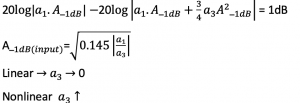
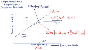
In this equation, a linear system a3 will be 0; therefore, A-1dB will be infinity, which means the system is completely linear. If the system is non-linear, then a3 increases and A-1dB decreases, reaching a point after which the gain starts falling.
In summary, if we have a system with very low input amplitude, then there will be no problem; however, when the input increases, it reaches a point called A-1dB, after which increasing the input will result in decreased gain, and this is called gain compression.


