Drawbacks of Non-linear System: Harmonic Distortion
In the previous section effects of Non-Linearity in RF systems, we read about non-linearity and its impact on the RF system. This section shows the drawbacks or problems faced with having a non-linear system.

In this example, there is a non-linear system with input x(t)=Acos wt and output y(t)=a1.x +a2.x2+a3.x3, and we know that ‘a’ is the gain and a2.x2 & a3.x3 are 2nd and 3rd order non-linearity, respectively. Using these two equations for input and output, we could determine the harmonic distortion in the system.
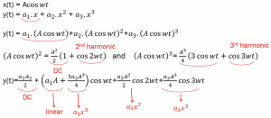
As shown in the equations, the input to our system has one fundamental frequency represented by x(t)=Acos wt with one cosine wave, but at the output get DC and three different kinds of frequencies. That is one of the drawbacks of having a non-linear system. The system produces harmonics, and they are called harmonic distortion.
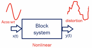
As shown in the diagram, we get a distorted wave at the output due to the two additional terms in the equation that corrupts the signal.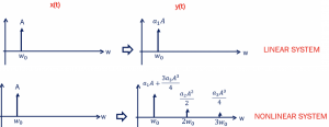
Comparing the linear and non-linear systems in the frequency domain, we could see the harmonic distortion. In a linear system with the input x(t), we get output with only one fundamental frequency with gain a1. Whereas in the non-linear system, there are three terms with different gain, and there can be even more terms, but they are ignored as the value becomes small after 3rd term.
With having these two additional terms, the kind of problems faced in a non-linear system can be explained using an example from the Book- RF Microelectronics 2nd edition B.Razavi P.16
Example: If we have a transmitter in 900-MHz GSM cellphone that delivers 1 W of Power to an antenna, explain harmonics’ effect.
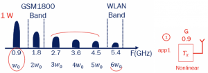
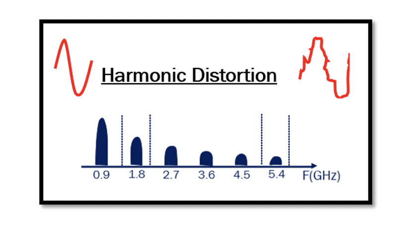
Let’s say the transmitter here is a non-linear system; therefore, it would produce harmonics. The transmitter is connected to the antenna and has to deliver 0.9GHz 1W Power. As it is non-linear, it produces harmonic distortion, which can see in the diagram; 1.8, 2.7, 3.6, 4.5, 5.4…..
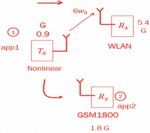
The second harmonic at 1.8GHz is in the GSM1800 band. Suppose we have another application (2) whose receiver works in this band, then it would receive the harmonic signal that is undesirable for its band and would be considered as noise. Producing harmonics is adding noise to the bands that are not meant to receive that signal. Harmonics corrupts or interferes with other system receivers around. The 6th harmonic at 5.4 GHz operates in the WLAN band; therefore, having a receiver for this band will receive the harmonic signal and have a comparable value will distort the WLAN band signals.
This is one of the main problems that we always try to avoid in the non-linear system as we produce harmonics. There is the distortion of signals and the creation of signals that can interfere with other systems around us. Harmonics are considered unwanted signals or noise for other applications. One solution is to use filters to prevent this problem, for example, a bandpass filter to smooth out the desired signal and get rid of other terms. A filter between the transmitter and antenna does the job, as it attenuates the undesirable harmonics from transmitting.

Learn more about this topic by taking the complete course ‘’RF Design Theory and Principles – RAHRF201’’.
Watch the course videos for more detailed understanding. Also checkout other courses on RF system and IC design on https://rahsoft.com/courses/
Rahsoft also provides a certificate on Radio Frequency. All the courses offer step by step approach.


