Drawbacks of Non-linear Systems: Desensitization effect
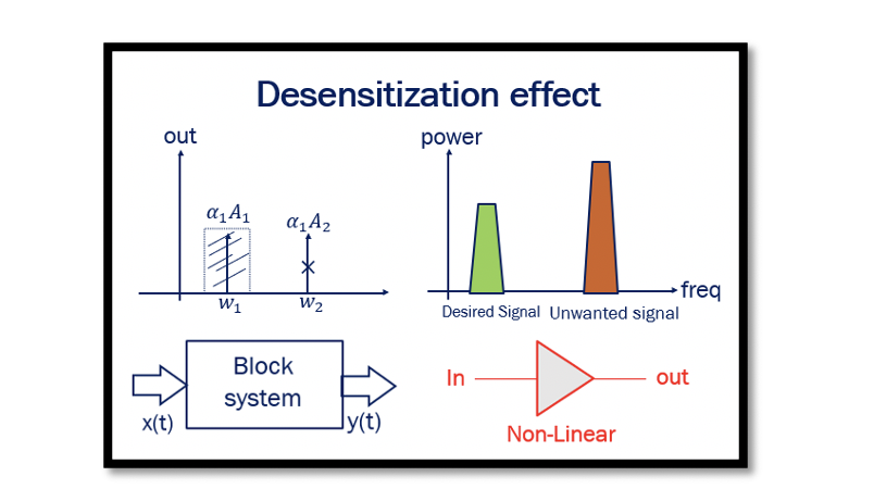
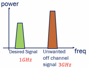
The third drawback of a non-linear system is the desensitization effect. The previous two drawbacks were Harmonic Distortion and Gain Compression. The below figure shows the condition where we have the desired signal and unwanted signal (noise). The unwanted off-channel signal is coming from another application; hence it is called off-channel signal. We need only the desired signal within our channel. The antenna of our system captures the unwanted signal as well, and it cannot be attenuated much, as the amplitude of the unwanted signal is much higher.
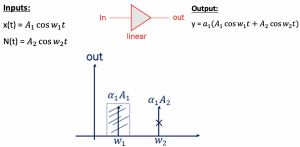
Assume that we have a linear amplifier, and inputs to the linear amplifier are x(t) and N(t), representing the desired and unwanted signals respectively. N(t) has frequency w2 and higher amplitude A2. At the output, we get y(t) which can be represented as shown:

Using a filter following the amplifier can remove the unwanted signal, as it is far away from the desired signal and the channel. Therefore, the unwanted signal can be eventually removed for a linear system using a filter, and it doesn’t have to be a very high order filter. For a non-linear system, if we have inputs x(t) and N(t) going into the non-linear amplifier, then y(t) can be written with 2nd and 3rd order non-linearity, and we get a complex equation:


![]()
Observing the outputs from the non-linear system, we see that the first term represented in green is similar to that in the linear system. The desired signal can be achieved by using a filter.
![]()

Plotting these four frequencies, we see w1 is far away from other components; therefore, a bandpass filter can be used to get the desired signal.

The 3rd order is the most important part. We have ten different frequencies in 3rd order non-linearity. In non-linearity with just two additional terms, we get 16 different frequencies. The linear system has only two components.
Out of these 16 different frequencies, many of them can be removed using filters. The components 2, 3, 4, 6, 7, 8, 9, & 10 can be removed as they are quite far from w1 and can be attenuated using filters.
The noise in a non-linear system is broken down into many different components that can fall into the desired band. The left components which fall into the band of w1 are:

A1 is much smaller than A2, as the noise’s amplitude is high. Therefore, the first component in this equation can be ignored.


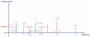
When all the components are represented, we get the following spectrum shown above, representing the different frequency components. The 1st part of the above equation is considered 0 as it is very small. The 2nd component in the above equation falls in the desired band, as shown in the diagram, which cannot be ignored. Using a filter, all other components can be attenuated. However, the blocker remains in the desired band. If A2 is high enough, it can decrease the gain or block our system’s signal. This A2 can cause the compression in gain, and this effect is called the desensitization effect.


