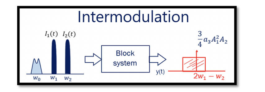
Introduction to Intermodulation in Non-Linear System
Intermodulation is the most important drawback of a non-linear system. It is similar to the desensitization effect discussed in previous sections. In this case, instead of one signal, we have two unwanted signals with high amplitude than the desired signal, and they are called interferer.
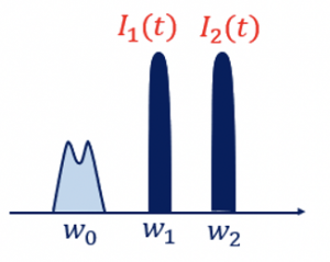
There are two conditions to note in intermodulation:
- w1 and w2 are close to each other
- w1, and w2 are close to the desired channel.
The figure assumes that the desired channel is 1GHz with w1 at 1.9GHz and w2 at 2.1GHz. These two signals are close to each other, and they are also close to the desired channel.
In the desensitization section, w1 and w2 were the input signals to the system where w1 was the desired signal and w2 was the unwanted signal; however, in this case w1 and w2 both are the unwanted signals with amplitude A1 and A2.
The output for this non-linear system can be expressed in the same way as we did in desensitization section:

![]()
Observing the outputs from the non-linear system, we see that the first term represented in green, the output is similar to that in the linear system. The desired signal can be achieved by using a filter. If the selected channel ranges from 1.2GHz to 1.8GHz with w1 and w2 around 1.9GHz and 2.1GHz, respectively, then with the center frequency of 1.5GHz, the desired signal can be filtered using a high-end bandpass filter.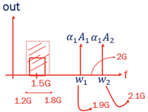
![]()
In the 2nd term non-linearity, we get four different frequencies values, having DC values, 2w1, 2w2, w1+w2, and w2–w1. The DC part can be filtered using a filter. The frequencies 2w1, 2w2, and w1+w2 can be ignored as they are higher values. The w2–w1 is a lower value with 0.2GHz and can also be filtered. Plotting these four frequencies, we see w1 can be filtered using a bandpass filter to get the desired signal.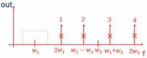

There are have ten different frequency components in 3rd order non-linearity. The linear system has only two components, but in non-linearity, we get 16 different frequencies in total. Out of these 16 different frequencies, most of them can be removed using filters. The components 1, 2, 3, 4, 5, 7, 8 & 10 can be removed as they are quite far from w1 and can be attenuated using a filter.
As we can see that frequency 9 falls within the desired signal channel range (1.2-1.8GHz). This signal is called the blocker signal that falls within the desired band.
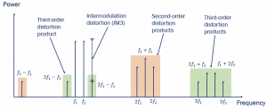 The above figure shows the spectrum of these frequency components. When all the components are represented, we get the this spectrum representing the different frequency components. Using a filter, all other components can be attenuated. However, the blocker remains in the desired band. The blocker decreases the gain or blocks our system’s signal which causes the compression in gain.
In summary, if we have a channel that is close to two interferer signals coming from another application with higher frequency and amplitudes, we get a blocker within the desired channel. One of the 16 frequencies in the spectrum acts as a blocker to the desired channel with amplitude A1 and A2 (for simplification, we can write A1=A2=A). Therefore, when two interferer signals with frequencies close to each other and close to the desired channel are captured by a non-linear system, intermodulation occurs.


