Non-linearity in Cascaded Stages
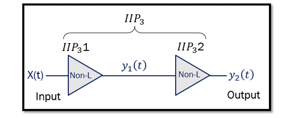
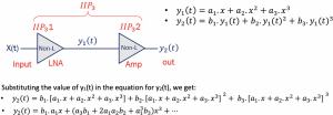
The design of an RF system consists of many different blocks, and sometimes it might include two amplifiers to amplify the weak signal. For example, the below figure shows the design with LNA and an additional amplifier for amplifying the weak signal. To calculate the IIP3 (third-order intermodulation product) for the whole system, assume the input to the LNA is x(t), and the output is y2(t). The equation for this system can be written as:
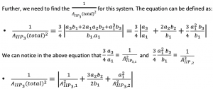
We already know that generally, the output of a non-linear system is written in the form of ‘’a1.in +a2.in2+a3.in3’’. From the section Intermodulation explained with examples, the AIIP3 can be written as:

From these equations, we can say that the AIIP3 is decreased for this system as there are two additional terms in the equation:
So the conclusion is if we add another stage to our amplifier, the total IIP3 will decrease, and the system’s non-linearity will increase. Therefore, adding another stage will significantly reduce AIIP3.
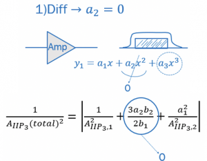
We know that for a differential system, the second term non-linearity is equal to 0. Similarly, in this equation, the second term (a2 & b2) can be ignored and considered 0. In RF systems, we always design amplifier for a range, and it is tuned.
 For example, consider this amplifier is working in a broadband frequency range of 3-5GHz. In the intermodulation section, we showed around 16 different frequency components in the spectrum. The 2nd order non-linearity frequency components a2x2 were out of the desired signal band, which can be ignored. When an amplifier is tuned, the second-order term is also omitted. The amplifier will automatically attenuate this term, as there is an inbuilt filter within the amplifier design. When we have a second system, then the IIP3 of the second system is multiplied by the gain of the first system. In the above equation, a12 is the gain of the first system. IIP3 contribution of proceeding stage is divided by gain of the previous stage.
If you see the equation, to improve the total AIIP3, the A2IIP3,2 have to be increased, making the second system more linear. Therefore, the right-hand side of the equation decreases, and we get a better value for total AIIP3.
While having a second system, the IIP3 value has to be more than the previous system, or we can say that the last stage should be linear than other stages if we want to have a linear system. There can be another case where the input to the first amplifier is really small. Hence, the system will act as a linear system; however, the amplitude is comparatively high after amplification when it enters the second amplifier. The second system might show non-linear behaviour. Therefore the system has to be designed such that we get high linearity from the whole system.

Learn more about this topic by taking the complete course ‘’RF Design Theory and Principles – RAHRF201’’.
Watch the course videos for more detailed understanding. Also checkout other courses on RF system and IC design on https://rahsoft.com/courses/
Rahsoft also provides a certificate on Radio Frequency. All the courses offer step by step approach.
Tag:Cascaded stages, IIP3, Non-linearity


