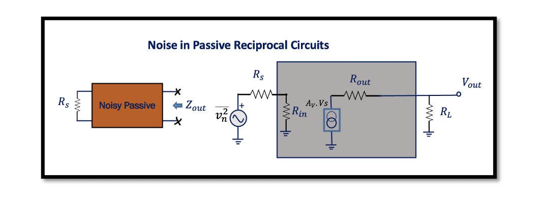
Noise in Passive Reciprocal Circuits
The network that consists entirely of linear passive components like resistors, capacitors, and inductors is usually called reciprocal. As it has passive elements, it’s a passive circuit, and it doesn’t have a transistor.
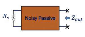
The above figure shows an example consisting of a bandpass filter which is a passive reciprocal circuit. The point to remember here is we never use resistors in a bandpass filter. If the average power of a resistor is positive, the resistor will absorb the power, leading to power loss. Hence, capacitors and inductors are preferred as reactive elements to avoid power loss and have a passive circuit.
How to find the output noise in a passive circuit?
As we know from the previous examples that NF is:
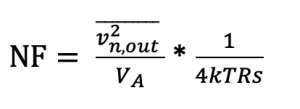
In theory, if the real part of impedance between two terminals of passive networks is equal to Real (Zout), then the PSD of thermal noise seen between these two terminals is given by:

Whenever we have this kind of passive circuit, we can model this circuit like shown below, and now we can find the output noise: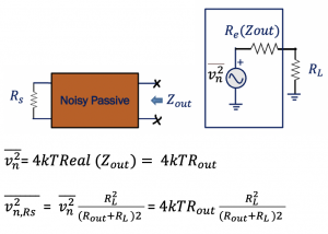
This is the output noise that we get from this kind of circuit.
In passive reciprocal circuits, Noise Figure (NF) is equal to the loss of the circuit. The NF is proportional to the loss of the circuit. The noisier a circuit is, the more loss it has.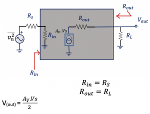
To prove that NF is proportional to noise, this is an example shown with a model. Where the input resistance is Rin and output resistance is Rout, and this is a matched circuit so that Rs will be equal to RL for this system.
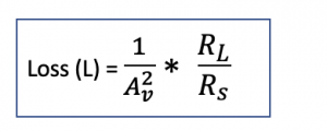
Now finding out the loss: Loss is equal to Pin by Pout (the power at the input to power at the output), and also loss is the inverse of power gain.
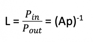
Finding the power at the input:
Due to two equal resistances, here the voltage will be divided by two, and if we want to find the power Pin:
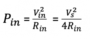
Similarly finding the Pout we get:
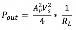
Therefore, the loss would be calculated as:
Now calculating the Noise Figure, we get:
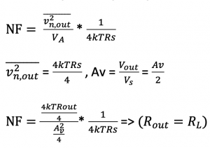
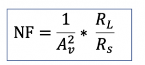
As we could see from the equations that NF is equal to the loss.
How can we decrease loss in our passive circuit?
Take an example here, and if we have a 5th order bandpass filter and a 3rd order bandpass filter, then we can say that the noise figure for the 5th order bandpass filter circuit is high as the filter has high order and elements are more compared to the 3rd order filter. More elements mean more noise sources. So NF2 is higher than NF1. Therefore we can say a loss for the 5th order is higher than the 3rd order.
- BPF 3rd -> NF1 NF2 > NF1
- BPF 5th -> NF2. L2 > L1
If the passive circuit is made more complicated using more elements, we will have high noise and consequently high loss. Therefore, to avoid loss, we try to make our passive circuit system as simple as we can to avoid a loss to avoid a high noisy number of circuit.

Learn more about this topic by taking the complete course ‘’RF Design Theory and Principles – RAHRF201’’.
Watch the course videos for more detailed understanding. Also checkout other courses on RF system and IC design on https://rahsoft.com/courses/
Rahsoft also provides a certificate on Radio Frequency. All the courses offer step by step approach.


