Understanding RLC Resonance Circuit in Series and Parallel
In radio frequency systems, passive networks and passive circuits are used to match or transform impedance. Passive networks are also used to tune the RF blocks, obtain desired input and output impedance, and design different filters. Therefore, it is important to understand the basic understanding of impedance transform and how a passive network works.
The components incapable of controlling current using another electrical signal are called the passive components, including resistors, inductors, and capacitors.
Parallel RLC resonance circuit
The below figure shows a parallel RLC circuit: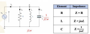
We will find the input impedance (Zin) of this network. jwL and 1/jwC are the impedances of the inductor and capacitor, respectively. The equivalent impedance for inductor and capacitor in parallel ZLC can be represented as shown in equation (2) below. Condition: If the denominator (1-w2LC) becomes 0 by tuning the resonance frequency w to 1/ √LC, then our circuit becomes infinity in resonance frequency.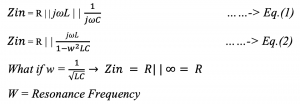
Behavior of RLC circuit in parallel
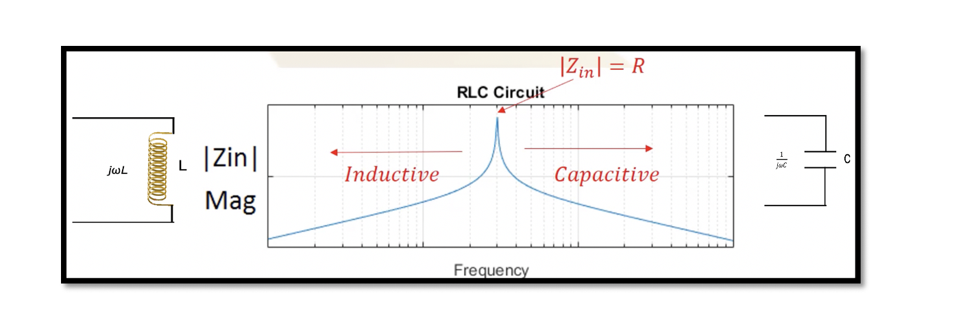
As shown in the below figure, there is a maximum magnitude of impedance that is equal to R. As we decrease the frequency, we don’t have resonance, the impedance will decrease at both inductive and capacitive regions.
For inductive region w is low, so w2LC<<1 and can be ignored. The input impedance Zin = jLw, if the frequency is less than the resonance frequency, the circuit acts as an inductor.
When w2LC>>1, then Zin = 1/jCw, which means the equivalent impedance acts as capacitance.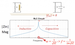
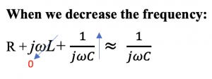
Similar behavior can be noted in phase. As we know, the phase of the inductor is always 90 deg. In the inductor region R | | jLw, when the frequency decreases, jLw becomes low, so the region becomes equal to jLw. In the capacitive region, R | | 1/jwC, when frequency increases, 1/jwC becomes small, and the region will be equal to 1/jwC.
In very high frequency, the circuit is capacitive, and in low frequency, the circuit acts as inductive.
Series RLC resonance circuit
At the resonance frequency, the input impedance will become equal to R.
In a parallel circuit, the maximum impedance occurs in the resonance frequency, but the minimum impedance occurs in the resonance frequency in a series circuit.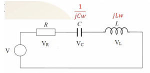
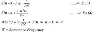
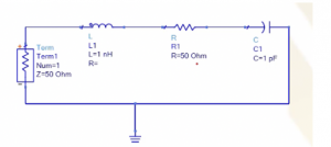
Simulation of series RLC circuit in ADS software
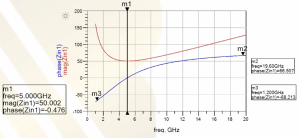
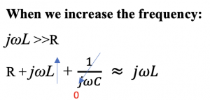
The RLC series circuit is simulated using the ADS software and the behaviour can be noted when it is plotted. It is inverse of what happens in parallel circuit. The resonance frequency here is 5 GHz and the magnitude is 50. As L & C becomes 0, the only component left is the resistor.
 .
. 