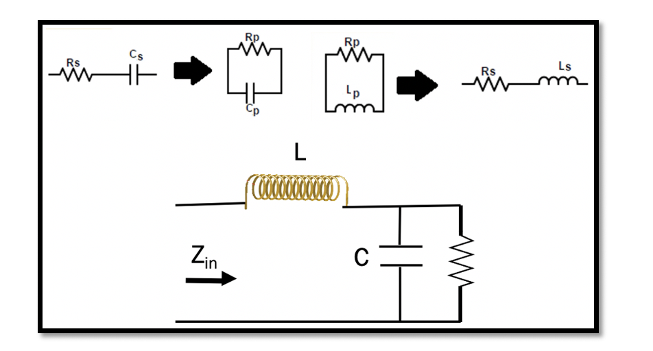
Understanding Resonance, Quality Factor and Series to Parallel Conversion
Resonance:
Resonance in a RLC circuit is when we cancel out all the reactants in the circuit. In RLC circuit L & C are the reactants. So the reactances of inductance and capacitance are essentially cancelled out, and only resistance is left in the circuit. Hence, at resonance we can say that the impedance consists only of resistance.
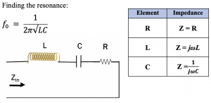
The quality factor tells the quality of our resonance, it can be determined by the ratio between the reactancts and the resistance, this ratio proves to be quite important. Calculating either of the reactances and comparing it with the size of resistance will gives the Q factor.
Quality Factor
The quality factor is defined as the ratio of resonance frequency (fr) to bandwidth; however, this definition is true only when there is resonance (L & C) in the circuit.
The common definition for quality factor is the ratio of the energy stored in the oscillating resonator to the energy dissipated per cycle.
Here, power loss is related to the resistor, and we don’t have power loss in the inductor or capacitor (as discussed in the section active and reactive power). The inductor and capacitor are dissipating or generating the reactive power, but when we say power loss, that is the active power related to the resistor in the circuit.
If we have more power loss, then we will have a low quality factor (Q). Low Q networks are not efficient due to more power loss. So the aim is to have high Q in the circuits.

Quality Factor is not only limited to RLC circuits. Q can be defined for networks having two elements. These circuits can be R with C or R with L. For example here are 4 circuit types with two components that can be represented with 4 different Q.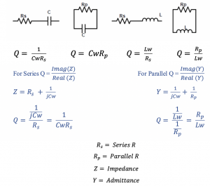
Series to Parallel Conversion
Method 1: Qs2 >> 1
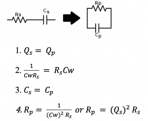
If we have series R & C, then it can be replaced by parallel equivalent circuit as shown below. The square of Qs should be higher than 1.
The process of this conversion includes few steps. The first step is to equalize the Quality Factor for both series and parallel circuits. When we convert the circuit the C becomes constant and only Rp changes.
Parallel to Series Conversion
Method 1: Qp2 >> 1
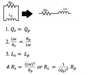
The circuit has inductor and resistor which can be converted to series equivalent circuit. The square of Qp should be higher than 1.
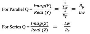
The first step is check Quality factor for both circuits and if square of Qp is higher than 1 then equalize the Quality Factor for both series and parallel circuits. When we convert the circuit the L becomes constant and only Rp changes.

Learn more about this topic by taking the complete course ‘’RF Design Theory and Principles – RAHRF201’’.
Watch the course videos for more detailed understanding. Also checkout other courses on RF system and IC design on https://rahsoft.com/courses/
Rahsoft also provides a certificate on Radio Frequency. All the courses offer step by step approach.


