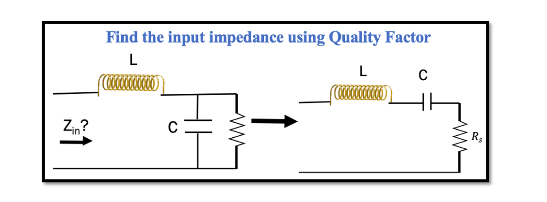
Calculating input impedance using Quality Factor and Resonance in RLC circuits
In the previous section, Resonance and Quality Factor we discussed the method 1 for series to parallel conversion and vice versa using Quality factor. To give a summary of method 1, this method is a process of conversion of series to parallel equivalent circuit following few steps when squared Quality Factor is more than 1 (Q2>>1). The first step to start with was equalizing the Quality Factor for both series and parallel circuits.
Example question using method 1:
Find the input impedance of the circuit below using the conversion method. Assuming Qp2 (CR) >> 1.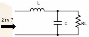
First, convert parallel C and R to series as shown below. Then equalizing the quality factors we get the value for Rs.
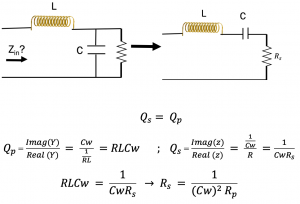
In resonance L and C becomes 0 so only Zin we have is Rs. Hence, the input impedance for this circuit will be equal to Rs.
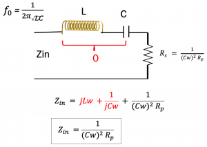
The second method to convert series to parallel circuit is squared quality factor is not higher than 1 (Q2 >/>1). An example of how we use to find the input impedance in this case is shown below.
Example question using method 2:
Find the input impedance of the circuit below using the conversion method when Q2 >/> 1 (when Q is not higher than 1).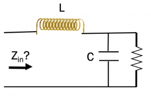
Method 2: Qs2 >/> 1
In this circuit R & C are parallel:
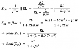
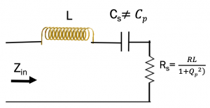
When we convert this parallel circuit to its equivalent circuit, as the Q2 is not higher than 1 we can say that Cs is not equal to Cp anymore. If we replaced with the equivalent circuit, then the square of Q should be higher than 1.
Now we need to find Zin and find resonance frequency from it. How to find the resonance frequency? We have to say that the imaginary part of Zin should be 0.

In method 1 we discussed that when quality factor is higher than 1 (Qp2 >> 1), we can see we get the same results:

In summary we can say that we can use method 1 for converting series to parallel and vice versa, however it has one condition Q2 should be really higher than 1. If this condition is not met, then input impedance Zin have to be calculated directly, then finding the real part of input impedance which is the series impedance and make the imaginary part equal to 0, then finally using the equation to find L as shown in the above calculations.

Learn more about this topic by taking the complete course ‘’RF Design Theory and Principles – RAHRF201’’.
Watch the course videos for more detailed understanding. Also checkout other courses on RF system and IC design on https://rahsoft.com/courses/
Rahsoft also provides a certificate on Radio Frequency. All the courses offer step by step approach.


