RF Receiver Architecture and Channel Selection
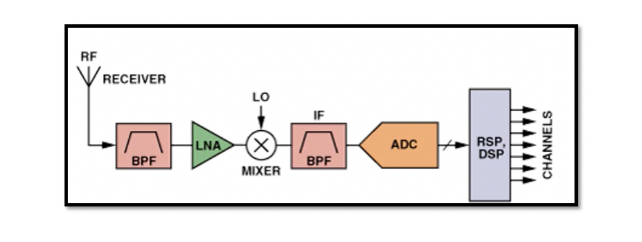
An RF module is a block that has sub-blocks inside it. It is a small electronic circuit used to transmit and receive radio waves on one of a number of carrier frequencies. These carrier waves have high frequencies. RF module is a functional integration of semiconductor devices. Examples: 802.11/WLAN, 802.15.4/Zigbee, Bluetooth, Bluetooth Accessories, GPS, proprietary RFID, UHF. All these devices have their own RF module and circuitry. The diagram shows a very simple RF receiver architecture which has blocks like Band-Pass Filter (BPF), Low Noise Amplifier (LNA), LO-Mixer, and analog-to-digital converter.
RF Receiver
A radio frequency receiver is a device that receives radio waves carrying information (called carrier waves) and coverts the data into a usable form. However, the data carried by the radio waves have been modulated; hence, they are not usable; therefore, the data has to be separated from the carrier wave, which is done by the receiver.
A radio frequency receiver can be an integrated circuit (IC) within another device. There is an antenna connected to the receiver. The antenna intercepts the electromagnetic radio waves, converting them to alternating currents before applying them to the receiver.
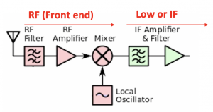
In a radio receiver circuit, the Front End (FE) is a generic term for the circuit between antenna up to and including mixer block. FE circuitry inside the receiver consists of the components that process the signal at an incoming frequency from the transmitter before converting it to a low or intermediate frequency. The below diagram shows receiver front-end components.

Band and Channel
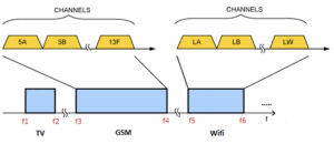
The band is the frequency range that is allocated to a specific application. Channel is the frequency range that is assigned to the particular user. So there is the band in a frequency range defined for different kinds of applications. Inside the band, we have lots of channels that are separated from each other. So first, we choose the desired band and then the desired channel. So when we say our receiver is a GSM band, we cannot receive any signal from other bands like Wifi.

Band selection in a receiver
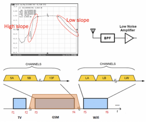
In a receiver, there is a bandpass filter between the antenna and a low noise filter. An off-chip bandpass filter is mostly used for choosing the desired band in a receiver. The input impedance of this off-chip bandpass filter is 50 ohms to match the antenna, and the output is also 50 ohms. The benefit of using this filter is to choose the desired band. Most of the filters are not symmetrical; for example, as shown in the figure for the GSM band, the lower end corner of the GSM band has a high slope and is steep compared to the higher end corner of the filter that has lower slope means low attenuation. Therefore, the signal coming towards the higher end of the band is less attenuated than the signals close to the lower end corner. If we compare TV, GSM, and Wifi in this example, the signals coming from TV are attenuated very well compared to the signals from Wifi which won’t be attenuated that much. An example of a bandpass filter is the SAW filter which is one of the off-chip filters used these days.

Channel selection in a receiver
First, the band is selected, and then the channel is selected. Channels are very close to each other hence. high Q filter is required to select a channel; however, it is unlikely to design so high Q filters in high frequency for choosing the desired channel. So first, the down conversion is done to bring down all the frequencies to IF or low frequency, and then in IF, we will be able to design a high Q filter even using active devices to select the appropriate channel.
What happens during down conversion for selecting a channel in a receiver?
We have a band, and we always select a band using the bandpass filter (BPF) at the beginning of the receiver. After selecting the band, the desired channel is chosen because, in high frequency, we cannot make a filter with high Q. Hence, the data signal recevied from the antenna is shifted to IF, and now a high Q filter can be designed with active elements to pick the channel successfully.

Learn more about this topic by taking the complete course ‘RF System Design of Receivers, Transmitters & Transceivers – RAHRF409’. Watch the course videos for more detailed understanding. Also checkout other courses on RF system and IC design on https://rahsoft.com/courses/.
Rahsoft also provides a certificate on Radio Frequency. All the courses offer step by step approach.


