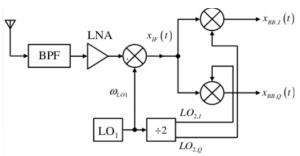
Overview of Zero IF Heterodyne Receiver
Zero-IF receiver
In zero-IF heterodyne receivers with quadrature down conversion have two steps for converting the channel. The first one is first IF the second one is zero IF. Then we have a low pass filter to filter the higher frequencies and send our data. Finally, we will send our digital processing to restore the channel and perform the demodulation as we always receive the modulated signal.
Imagine that the receiver is working on 3 to 5 GHz and the antenna receives the band, so then we have to design a bandpass filter which is the only off-chip element in this structure, it can be a SAW filter that works between 3 to 5GHz attenuating any other signal outside the band limit. As we discussed before that, to remove the image signal, we have a second bandpass filter (image reject filter) which is now a part of the LNA network. Modern receivers have the filter designed on-chip, that is, the LNA is tuned. This LNA is narrow-band, it has a tuning circuit, and it acts like an image reject filter. If the LNA tuning range is 3 to 5 GHz, it is designed to amplify signals in 3 to 5 GHz, and it does not amplify interferers in the image band. Usually, a mild on-chip bandpass filter can be inserted after LNA to suppress the first image signal. After that, there is the mixer for down-conversion, and then comes the quadrature down conversion to restore our data before demodulation through digital data processing. This is the purpose of using this kind of structure so that we can restore our data and solve the problem where the signal becomes its own image.

Sliding-IF Receivers
In the figure above, we saw three mixers in the structure for the zero-IF heterodyne receiver, which means three local oscillators. The first oscillator was for RF and the next two for producing cosine and sine signals for quadrature down conversion. However, modern real-time receivers do not employ three oscillators. Therefore, we only have one oscillator that produces three frequencies. The second LO is derived from the first LO by using a frequency divider.

The first one is getting from LO1, but the second one is half of LO1, so it has half the frequency of the first local oscillator. This is called a sliding RF receiver. We divide the second oscillator frequency by 2 (it can be 4 or 8 as well). The design of oscillators and frequency synthesizers are difficult. We can’t design three oscillators as oscillators fabricated on the same chip suffers from unwanted coupling, if we design a couple of oscillators, they will start coupling with each other, and hence, we will have problems. Therefore, it is preferred not to design many local oscillators but to design only one LO, and the second LO is derived from the first LO by using a frequency divider.
So as we know, there is quadrature down-conversion, and we need cosine and sine waves to restore our data; therefore, the frequency divider block is doing the 90-degree phase shift producing two outputs. So the frequency divider has two tasks first, to divide the frequency, and the second task is to do the 90-degree phase shift. Hence the two signals that are produced by the frequency divider have a 90-degree phase difference. So the frequency divider produces these two outputs:


