Drawbacks of Quadrature Down Conversion
What is the drawback of quadrature down conversion?
In this blog, we will be looking into the IQ mismatch and how it affects our signal. Refreshing the memory from a previous blog on Quadrature down conversion. Looking at the below structure we can see the quadrature down conversion uses two mixers, one fed with a cosine carrier wave (B cos ωct) and the other with a sine wave (B sin ωct), B is the amplitude. The purpose of using the quadrature down conversion is that the data can be restored. In short what we discussed in the blog was if we get I(t) and Q(t) and do digital signal processing, we can get I(n), and for Q(n) we multiply by -j and then add these two together to restore our signal. Read about quadrature-down conversion and how to reconstruct the original data.
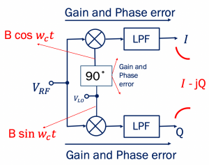
The quadrature down conversion is used to avoid the image problem that is faced in the zero-IF receiver. In quadrature down conversion, we create two versions of the down-converted signal with a phase difference of 90 degrees. So basically, we are creating quadrature signals. However, this structure is not perfect and does have some errors that we will be discussing in this blog. We can have phase and amplitude errors. The system cannot be precise so it cannot be exactly 90 degrees, we can have phase and amplitude errors in that case. The two mixers cannot be identical they can have amplitude errors for example the gain of one mixer can be different from the other one, so we have to be careful while designing these structures.
What is an I/Q mismatch?
Error in the 90˚ phase shift circuit and mismatches between the quadrature mixers result in imbalances in the amplitude and phases of baseband I and Q outputs. So if there is a mismatch between I and Q the data cannot be completely restored properly and hence there will be data errors.
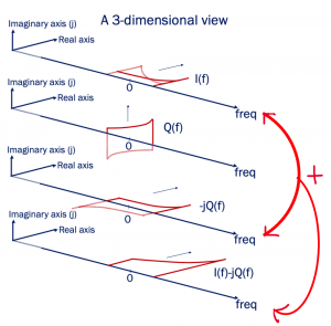

As discussed in the previous blog, to restore the data, first, we multiplied Q(f) with -j and added the two signals together, the dotted part, which is the image channel, gets cancelled out, and the channel can be restored This is the purpose of using this kind of structure as in the end, we can restore our data and solve the problem where the signal becomes its own image. But let’s see what happens if we have a little bit of phase or gain error here.
The two dotted part in the below image gets cancelled out. This happens only when they are identical and precise systems and have the same gain and amplitude with a 90˚ phase shift. However, if the parameters are not identical and there is an error then we will have data errors because of an I/Q mismatch.
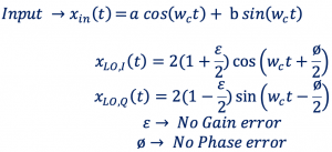
Case 1: When there is 0 gain and phase error
 .
. 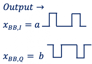
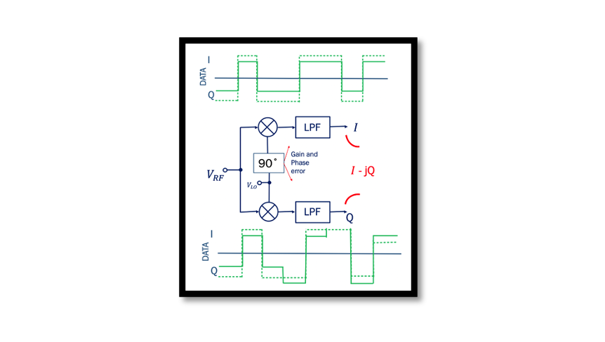
Assume this is a perfect system with no gain or phase error. The input (xin) is an RF input from a direct conversion receiver and it’s a QPSK signal that is it’s a modulated signal. (Knowledge of QPSK modulation is needed here). Briefly talking, when we have modulation data for a QPSK signal we expect to get back a or b as output (pulse) when we demodulate the signal.
Case 2: When there is a gain and phase error
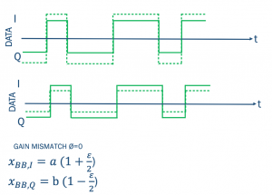
At the baseband, we should be getting 1 or 0 after demodulation but due to an error we have the output something like this as shown below:
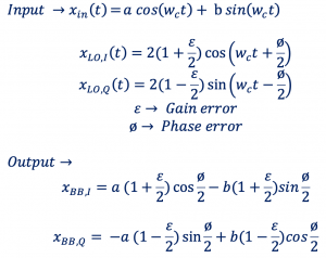
Let’s see the effect of this error: the dotted lines show the mismatch error. As there is an error we can see that we are getting more or less amplitude than expected, shown by the dotted black lines.
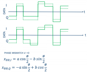
How to rectify the Gain and Phase error in the circuit (I/Q mismatch)?
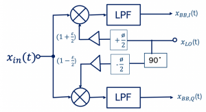
The solution to this problem is easy, use a digital adaptation for this method. The below image represents how its implemented. So instead of using an antenna and LNA, we keep the same modulated signal from another input in order to test, the below image shows the test process.

Assume that we have pain and phase error as indicated. By tuning we can fix it and bring it back to the desired position. Let’s assume the gain error is ε, the logic will detect this gain error at the output because it’s digital logic so it will be able to process the data and find the error. After which the logic will provide feedback to the amplifier. For example, if the gain is high so imagine the gain for this amplifier is supposed to be 10 but because of the gain error ε it’s 9. Then the logic will detect this and increase the gain back to 10 again. So basically this logic is kind of a controller so it will detect the phase and the gain error then through the feedback it will tune the circuit. With these two feedbacks, it will tune the circuit and compensate for the gain and phase error.


