Understanding ‘Constellation-Distortions’
Have you ever tried exploiting constellation diagrams to locate the source of bugs in your wireless link? Yes! digital communication systems can be diagnosed for several impairments by visual inspection of constellations diagrams. One may ask why we want to use constellation diagrams for troubleshooting while we do have EVM as vital performance metric of communication systems? So, be reminded that EVM only quantifies the performance of wireless link without highlighting the cause of errors unlike constellation diagrams that point-out the potential sources of errors. In short, EVM is used to quantify the degradation against specifications and constellation diagram is examined to locate the sources of degradation.
Phase Noise errors
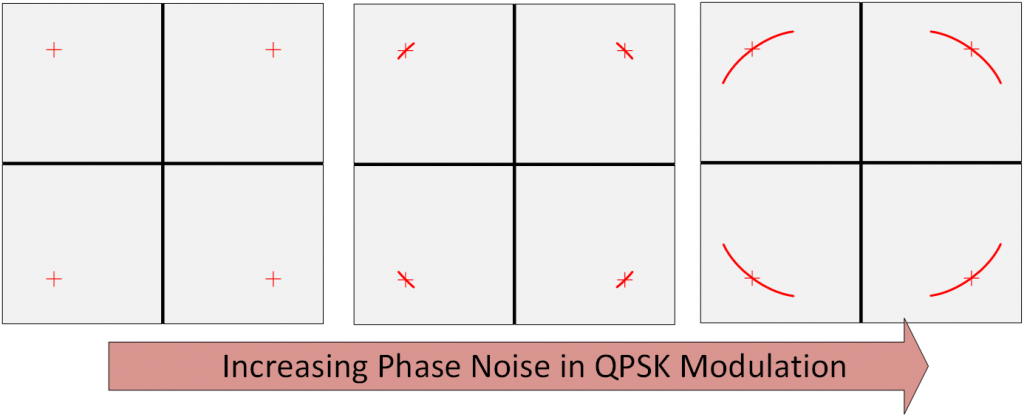
Phase Noise is undesired modulation of carrier which causes constellation points to rotate around the origin and so, forces the boundary regions to come closer to each other resulting in increased EVM and BER. Phase noise is usually introduced by transmitter or receiver and not by the channel. Read more…
Compression effects
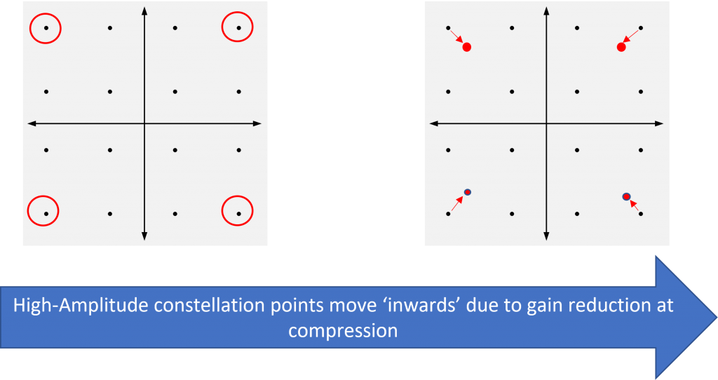
Compression or saturation means lowering of transmitter/receiver gain for high-power signals. Compression causes farthest points (from the origin) in constellation diagrams to be “pulled-in” as they are of the maximum amplitude (and suffer the most from compression effects). This distortion might arise due to the compression of either of transmitter or receiver, and results in increased EVM and BER.
Wideband noise (low SNR)
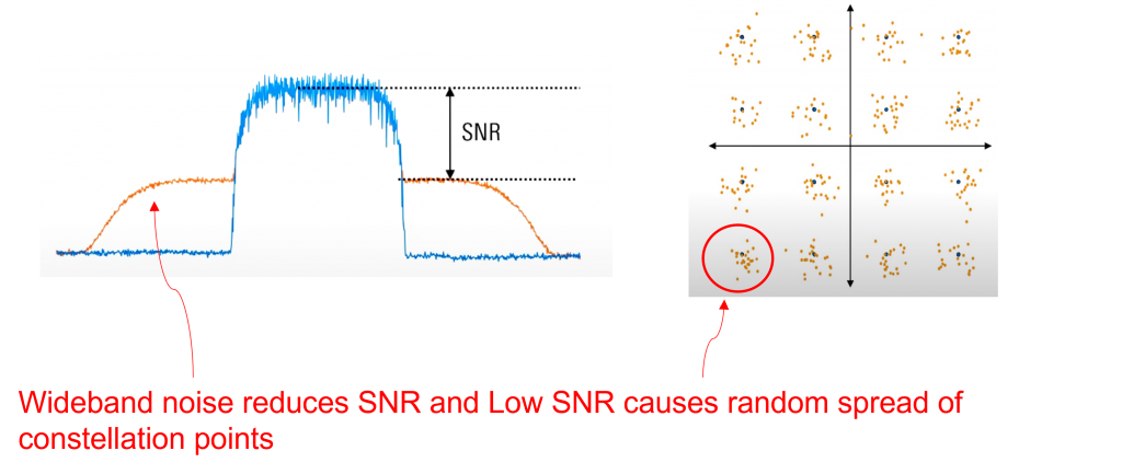
Wideband noise lowers the Receiver SNR. Note that SNR degradation is usually caused by high Noise Figure of the receiver. Low SNR causes the constellation points to spread out randomly around their ideal positions: Lower the SNR, higher the spread and EVM (BER).
in-band Spurs/interferers
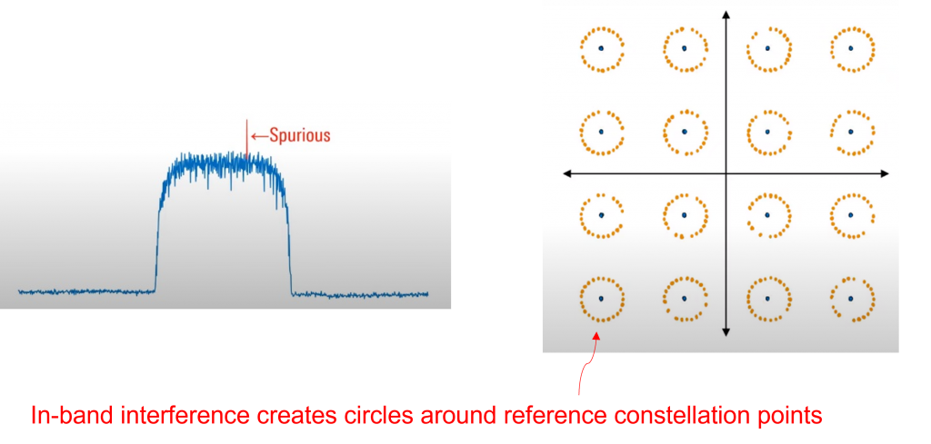
Narrow-band Spurs within signal bandwidth causes constellation points to create circles around their ideal positions. As the power level of in-band spurs increases, the radius of the circles increases resulting in higher EVM and BER.
IQ imperfections
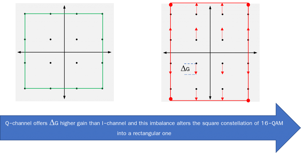
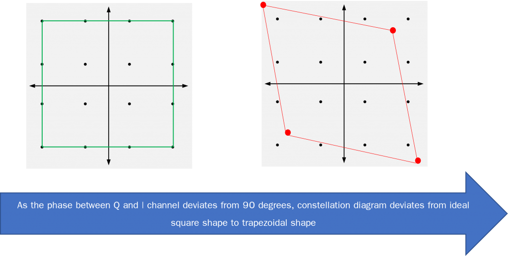
IQ modulations require the IQ modulators (transmitters) and demodulators (receivers) to have equal gains in I and Q channels whereas 90 degrees of phase shift is needed to be maintained across the frequency band of operation. However, this balance is practically not possible resulting in constellation distortion as explained below. Note that 16-QAM modulation is used as an example to illustrate the IQ imperfection issues
(a) Gain imbalance causes the Constellation diagram to be stretched in one direction, resulting in rectangular shape instead of square.
(b) Phase imbalance causes the Constellation diagram to be tilted, resulting in trapezoidal shape instead of ideal square. Note that a shift of outermost points only is shown in the figure below for explanation, whereas in actual, all the constellation points get displaced from their ideal positions as per phase imbalance. Deviation from ideal square shape of QAM constellation (due to either of the gain or phase imbalance) causes the EVM and BER to increase.

Learn more about this topic by taking the complete course ‘RF System Design of Receivers, Transmitters & Transceivers – RAHRF409’. Watch the course videos for more detailed understanding. Also, checkout other courses on RF system and IC design on https://rahsoft.com/courses/. Rahsoft also provides a certificate on Radio Frequency. All the courses offer step by step approach.
Tag:BER, Constellation distortion, EVM


