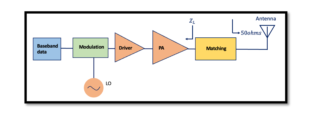
Analog Transmitters – Examples
Amplitude Modulation
RF signal utilizes the signal called carrier signals. In simple language it is just an AC signal at a set frequency, in other words, think of it as a link that connects the communication points. AC signals generate electromagnetic waves, and those waves are radiated into the air by the transmitter. The waves travel through the air and are received by the receiver. The carrier signal alone doesn’t transfer any information, in order to do that the information has to be encoded into the carrier, this process is called modulation. There are various modulation techniques ranging from simple to complex. The carrier establishes the information link and the information sent is modulated onto the carrier.
The oscillator is a device that produces a periodic sinusoidal waveform with low-phase noise. It converts DC to AC signal. The local oscillator (LO) produces the carrier frequency that’s fed to the mixer.
In AM the carrier signal is multiplied by the information being sent. The receiver performs the demodulation where the carrier signal is decoded, and information is extracted digitally.
Analog Modulation:
Modulation is the process of mixing a signal with a sinusoidal to produce a new signal. The sinusoidal signal that is used in the modulation is known as the carrier signal. The signal that is used in modulating the carrier signal is known as the data signal or message signal.
Analog modulation– AM, FM, PM
Digital Modulation:
Amplitude modulation – PAM, QAM
Phase modulation – PSK, DPSK, OPSK
Frequency modulation – FSK
Continuous phase modulation – GMSK, MSK, CPFSK
Trellis coded modulation – PSK, QAM
Transmitter for Amplitude Modulation:
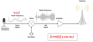
In the below diagram, the microphone produces an audio frequency that has low-frequency data. The microphone captures the sound and we have the audio signal, we can call this m(t). This signal m(t) has a low frequency, it can be an intermediate frequency. We are doing upconversion and modulation at the same time. Using the mixer we are doing upconversion and modulation at the same time.
[1+m(t)] signal is a DC value and we multiplied it by cosine wct and at the output, we have a radio frequency signal which is AM modulated signal and it has high amplitude. We call this amplitude modulation transmitter. Then this signal goes to the power amplifier and then the matching circuit. The power amplifier amplifies the modulated signal enough so that the antenna can radiate. This structure is a basic one just to show it simply.
Transmitter for FM modulation
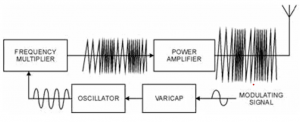
In FM modulation we are trying to modulate the frequency instead of the amplitude, so the amplitude is constant here. As you can see shown in below diagram we have Voltage Control Oscillator (VCO). The frequency of a VCO changes when we change the input at this block, so basically, we can connect this voltage to modulating signal. The data has a low frequency, the voltage is controlled by the varicap block. This is the modulation part as referenced in the below diagram, where the voltage of VCO is controlled. When data has high amplitude the oscillator produces high frequency and when data has low amplitude the frequency at the output of this oscillator decreases and after that frequency multiplier is used to increase the frequency to the RF.

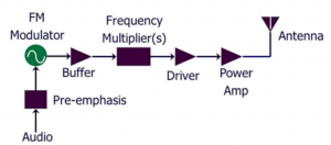
We have our audio signal block which goes to FM modulator, FM modulator as we talked about in the previous paragraph is the VCO, but it’s not alone VCO, we have to use PLL, Phase Locked Loop within this structure. So we send a voltage and get a frequency from FM. Then we have the buffer, frequency multiplier, driver, power amplifier, matching network within PA, and antenna.


