Design Challenges Faced by Transmitters
In this blog we will discuss about the challenges faced in designing RF transmitters, focusing on direct conversion transmitters.
I/Q mismatch
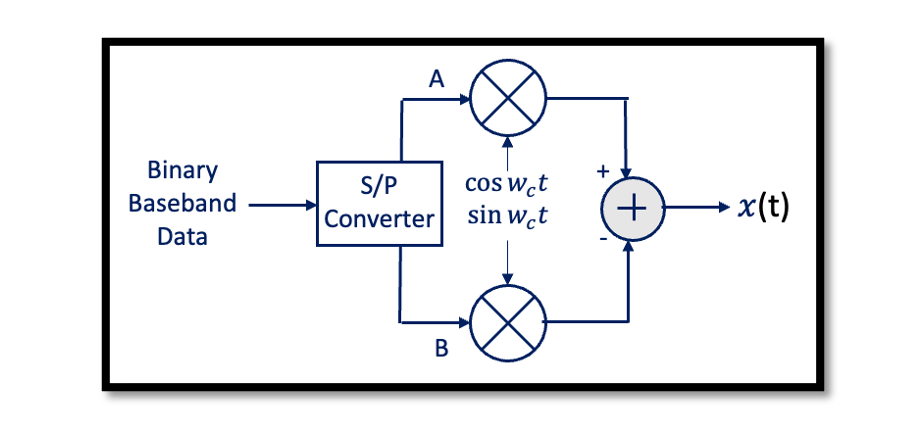
What is an I/Q mismatch? We have already discussed this before in receiver blogs and read about I/Q mismatch. Let’s use the QPSK system to show this problem. In receiver design as well we had a similar issue with I/Q mismatch. We will see the effect of the I/Q mismatch in the QPSK system. In the below architecture, A and B waves are produced from binary baseband data using serial to parallel converter (S/P Converter). These waves are pulses (1,-1) with a low frequency which will be upconverted using the quadrature upconverter. This is a direct upconversion from baseband to RF. Imagine the modulated signal is QPSK = A. Ac cos wct + B. Ac sin wct. So what kind of output we will have here if our system is a perfect system with no mismatch.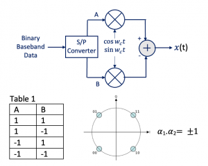
This is for a perfect system and if we send this kind of data we won’t have any problems. However, in a real scenario, the system is not perfect and we would have a mismatch. There are two kinds of mismatch: phase mismatch and amplitude mismatch. So we always want to have a 90-degree phase difference between these two carriers in the quadrature upconverter and the same amplitude however, there is always some error. As we discussed in the receiver part as well that we are trying to refer the mismatch to one part of our system and write it as:
So now after rewriting this we have the normalized amplitudes: If ∆ø and ∆Ac = 0 then we get back the results shown in Table 1.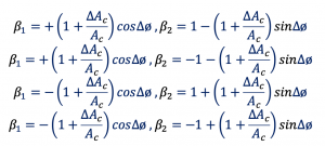 We are sending data with errors to the receiver, which is a problem, when the receiver receives this data and try to demodulate it they will have a bit of error which leads to one of the major problems faced in designing. So we have to be careful and match these two oscillators at the in-phase and quadrature part.
Calibration
How to eliminate I/Q mismatch?
There is a method to find the mismatch and eliminate it by tuning the circuit called the calibration method. In the calibration method first step is we are trying to find the phase mismatch. Let’s use the below structure for this as an example:
1. Eliminate Phase mismatch
Apply a single sinusoidal to both inputs of this transmitter to reveal a phase mismatch.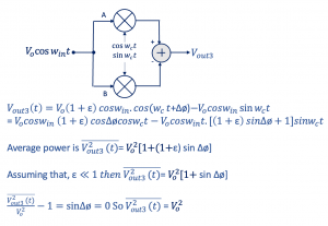 Then we find the average power of the wave. Let’s say the amplitude error is ε and the phase error is ∆ø. ε is generally less than 1 so we are ignoring 1+ ε. So in order to do the calibration we assume sin∆ø=0, so the phase error is 0. So we found the output power Vo2 which is the power of the sinusoidal wave Vocos wint. So what we are doing here is we are applying the sinusoidal wave at the input of our transmitter and the output in order to have 0 phase error we should get the same power. We can apply this power to the circuit and adjust and tune the circuit until we match the same power at the output. Which is a very good method to eliminate phase mismatch.
2. Eliminate gain mismatch
The next method is doing a gain mismatch. One side is grounded as shown in the diagram and feeds the cosine part with in-phase and we find Vout if you calculate in the formula for Vout:
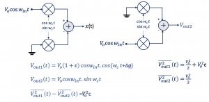
Then we find the average power of Vout1. Similarly, we can connect the in-phase part to the Vocos wint and this time calculate the output power. Basically when we find this and when we subtract this value that is Vout1-Vout2 here you see that the error should be zero which implies both powers should be exactly the same.

Learn more about this topic by taking the complete course ‘RF System Design of Receivers, Transmitters & Transceivers – RAHRF409’. Watch the course videos for more detailed understanding. Also checkout other courses on RF system and IC design on https://rahsoft.com/courses/. Rahsoft also provides a certificate on Radio Frequency. All the courses offer step by step approach.
Tag:I/Q mismatch, Transmitter


