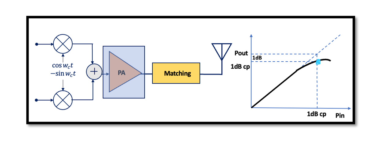
Transmitter Linearity
What is linearity?
Linearity is the property of a mathematical relationship or function, which can be graphically represented as a straight line. Linearity can be graphically represented as a straight line. We always expect to have this kind of outputs in our systems but actually in the real world it is bit hard and challenging to have a completely linear system, we end up having non-linearity.
In addition to the first term we had in linear system, there are two more terms called 2nd order non-linearity and 3rd order non-linearity. However, it is not limited to only two terms, and it can have more. As we proceed further, the terms after 3rd order become small and low for comparison; hence, they can be ignored sometimes. When the system is really sensitive, these terms are also taken into account.
Linearity in Transmitter
When it comes to linearity we have to be careful with the two blocks of the transmitter; the mixer and PA. The excessive non-linearity in the baseband port of the mixer can corrupt the signal or raise the adjacent channel power.
What is the adjacent channel? The adjacent channel is the channel or frequency that is directly above or below a specific channel or frequency. At the output of the transmitter we have something like this, with center frequency fc, let it be a GMSK modulation and the goal here is to have the signal power within the channel band but due to various drawbacks/problems we might have channels or power outside the band as shown as adj in the below diagram: 
These are unwanted adjacent channels that we do not want to have as these act as interferers for other channels and eventually, we are producing noise and we want to avoid these. Due to certain errors within the transmitter, the interferers are produced and we try to decrease the power around the channel. So one of the problems is mixer linearity.
Mixer Non-Linearity in Transmitter
In the baseband port of the mixer, we can have non-linearity due to the circuit of the baseband or the mixer itself. Referring to the above GMSK modulation circuit of the transmitter, previously we had a1Acosø and a1Asin ø but due to non-linearity, we have the 3rd component a3A3cos3ø which is the extra component. Let’s see what happens after mixing, at the output we have this equation:
We have the GMSK modulation part in the equation, but you can see we have extra components in the equation, a problem in the amplitude and which will corrupt the signal, this may decrease the value of the signal. So actually we are producing the two GMSK signals and the second one has higher bandwidth. In an ideal case, we are increasing power around our desired channel which means that we are giving rise to the power of an adjacent channel, we are not allowed to produce any power outside our channel here but because of this high bandwidth we are producing extra power, so this is the problem we are facing in linearity. In order to avoid having this problem, we have to design a linear mixer.
Power Amplifier Non-Linearity in Transmitter
Linearity becomes very critical at the last block of a cascade system (ignore the matching circuit). Let’s name the stages stage 1, stage 2, and stage 3. The signal here at the input of PA has a large swing and at the output a larger swing. So we say that the largest voltage swings occur at the output of PA, this stage dominates the linearity and compression of transmitters, so we have to be careful about the linearity of PA. As the linearity is critical here, we have to consider the compression point (cp).
What is a compression point?
It is a point in the graph where the difference in linear and non-linear amplifier’s output amplitude in fundamental frequency is 1dB. It can also be defined as the point where the non-linear amplifier’s output is 1dB less than the linear amplifier’s output. This compression point is used to measure non-linearity. Read more about Non-linear System: Gain Compression.
It means that if you want to have a linear system, we have to operate the PA before the compression point. We cannot increase the input power of this PA more than the value shown in the diagram above, it is the linear range so if you increase the power more than this value there will be a problem in linearity.

Learn more about this topic by taking the complete course ‘RF System Design of Receivers, Transmitters & Transceivers – RAHRF409’. Watch the course videos for more detailed understanding. Also checkout other courses on RF system and IC design on https://rahsoft.com/courses/. Rahsoft also provides a certificate on Radio Frequency. All the courses offer step by step approach.


