Quarter Wave Transmission Line
What is Quarter Wave Transmission Line?
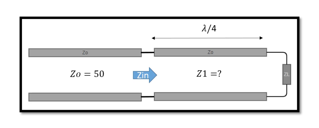
A quarter-wave transmission line has a characteristic impedance of Z0, which matches the impedance of the source and the load. The length of the quarter-wave line is chosen so that the impedance seen at the source end of the line matches the desired impedance.

The impedance transformation of a quarter-wave transmission line is based on the principle of electrical resonance. At a specific frequency, the impedance of the quarter-wave line is equal to the load impedance, which causes a maximum transfer of power from the source to the load. The quarter-wave line acts as an inductor or a capacitor depending on the load impedance.
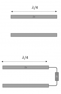
A quarter-wave transmission line is a type of transmission line that is designed to be one-quarter of the wavelength of the signal it is carrying. The length of the transmission line is given by L = λ / 4, where λ is the wavelength of the signal. A quarter-wave transmission line is commonly used for impedance matching in radio frequency (RF) circuits, antennas, and microwave systems.
If the load impedance ZL is zero, the input impedance of the quarter-wave transmission line becomes infinite. This is because at the open end of the transmission line, the voltage is at a maximum and the current is at a minimum, which results in a very high impedance.
If the load impedance ZL is not zero, a quarter-wave transmission line terminated by ZL can be used as a matching circuit. In this case, the input impedance Zin of the transmission line can be calculated using the following equation: Zin = Z02 / ZL
where Z0 is the characteristic impedance of the transmission line.
If the load impedance ZL is real, the input impedance of the transmission line will also be real. The transmission line can be used as a matching circuit by selecting a quarter-wave length that transforms the load impedance to the characteristic impedance of the transmission line. This is achieved by choosing the length of the transmission line such that the impedance seen at the input end of the transmission line is equal to the characteristic impedance Z0.
Examples of quarter wave transmission line
EXAMPLE 1:
For example, suppose we have a load impedance of ZL = 50 ohms and a characteristic impedance of Z0 = 75 ohms. To match the load impedance to the characteristic impedance, we can use a quarter-wave transmission line with a length of L = λ / 4 = v / (4f), where v is the velocity of propagation of the signal and f is the frequency of the signal. The resonant frequency of the circuit is given by f = v / (4L).
By selecting the appropriate length of the transmission line, the load impedance can be transformed to the characteristic impedance of the transmission line, resulting in maximum power transfer from the source to the load.
EXAMPLE 2:
Example of using a quarter-wave transmission line for impedance matching. Suppose we have a load impedance ZL of 100 ohms, and we want to match this to a transmission line with a characteristic impedance Z0 of 50 ohms. To do this, we can use a quarter-wave transmission line with a length of λ/4, where λ is the wavelength of the signal. First, we need to calculate the length of the quarter-wave transmission line. The wavelength λ is given by: λ = v/f
where v is the velocity of propagation of the signal and f is the frequency of the signal. Let’s assume that the signal has a frequency of 1 GHz, and the velocity of propagation is 2×10^8 m/s (the speed of light in a vacuum). This gives us a wavelength of λ = 0.2 m. The length of the quarter-wave transmission line is then:
L = λ/4 = 0.05 m
Next, we need to calculate the characteristic impedance Z1 of the quarter-wave transmission line. We can use the equation:
where Z0 is the characteristic impedance of the main transmission line (50 ohms) and ZL is the load impedance (100 ohms). Plugging in the values, we get:
Z1 = √(50 x 100) = 70.7 ohms
To plot the magnitude of the reflection coefficient Γin versus frequency, we need to calculate Γin using the equation:
Γin = (Zin – Z0) / (Zin + Z0)
where Zin is the input impedance of the circuit, which is given by:
Zin = Z0 x (Z1 + jZ0 x tan(2πfL/v)) / (Z0 + jZ1 x tan(2πfL/v))
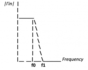
Plugging in the values for Z0, Z1, and L, we can calculate Γin as a function of frequency. We can then plot the magnitude of Γin versus frequency, as shown below: Where f0 is the resonant frequency of the circuit, at which the input impedance is matched to the characteristic impedance, and f1 is the frequency at which the reflection coefficient is maximum. The magnitude of Γin is at a minimum at the resonant frequency and increases as the frequency moves away from the resonant frequency. The bandwidth of the matching circuit is determined by the frequency range over which the magnitude of Γin is less than a certain threshold, such as 0.1 or 0.2.

Learn more about this topic by taking the complete course ‘RF Microwave and Radio Frequency Transmission Theory Online Course – RAHRF200’. Watch the course videos for more detailed understanding. Also checkout other courses on RF system and IC design on https://rahsoft.com/courses/. Rahsoft also provides a certificate on Radio Frequency. All the courses offer step by step approach.


