Understanding and Measuring Gain Flatness in Electronic Components
Introduction:
In the intricate world of electronic components, the concept of gain flatness emerges as a critical metric, wielding profound implications for the performance and reliability of active devices. This metric, expressed in decibels (dB), assesses the variation in gain exhibited by a Device Under Test (DUT) across predefined frequency bands or dynamic ranges. The pursuit of optimal gain flatness is paramount, as deviations in gain levels can lead to distortions, inaccuracies in output power, and potential disruptions in tightly regulated link budgets. In this exploration, we delve into the nuances of gain flatness measurements, unraveling the significance of this parameter in ensuring the seamless functionality of electronic systems.
Understanding Gain Flatness in Active Components
In the realm of active components with specified gains, the measurement of gain flatness becomes crucial. Gain flatness is commonly assessed over a particular frequency band or dynamic range, spanning from low to high input power levels. This dynamic range assessment, for instance, can range from 0dBm to 20dBm input power. Essentially expressed in decibels (dB), gain flatness represents the maximum variation in gain exhibited by a Device Under Test (DUT) across a specified frequency range or dynamic range.
Examining gain flatness becomes particularly significant because it provides insights into how linearly or non-linearly the gain behaves within the defined parameters. A noticeable variation between the maximum and minimum gain levels in the dynamic range can have substantial implications. Excessive gain variation has the potential to introduce distortion or result in inaccurate output power, especially in scenarios with stringent link budgets. The impact of gain flatness, which can extend up to 1-2dB, depends significantly on the specific application. To calculate gain flatness in dB, a straightforward formula is applied. It involves subtracting the minimum gain from the maximum gain obtained during the measurement process. Understanding and addressing gain flatness are crucial steps in ensuring the reliable performance of systems employing active components.

Conducting Gain Flatness Measurements Across Frequency Spectrum
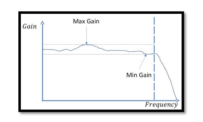
When measuring gain flatness across the frequency spectrum or bandwidth, pinpointing the maximum and minimum gains is pivotal. Imagine the frequency spectrum as a landscape, where the maximum gain occurs at a specific point, denoted perhaps by an arrow. Conversely, the minimum gain might manifest at another section, possibly near the cut-off frequency, where a discernible roll-off initiates. The difference between these extremities encapsulates the gain flatness.
To perform such measurements, the input power level of the Device Under Test (DUT) is held constant, maintaining a fixed output power from the RF source. The only variable in this scenario is the frequency, necessitating a sweeping of the RF source’s frequency while concurrently measuring the gain across the defined frequency band. This straightforward measurement involves a basic setup comprising the RF source, the DUT, and optionally a spectrum analyzer or power sensor. Depending on the application, additional components may be introduced into the setup. Nonetheless, the core principle of this measurement remains simple, making it an accessible and effective method for evaluating gain flatness across a frequency spectrum.
Measuring Gain Flatness with Real-world Examples:
Gain flatness, often measured over a frequency spectrum or dynamic range, finds practical significance in various applications. Consider a communication system where an amplifier processes signals across a broad frequency range. In this scenario, maintaining consistent gain becomes imperative to prevent signal distortion. For instance, a satellite communication system operating in the Ku-band (12-18 GHz) demands meticulous gain flatness measurements to ensure signal integrity throughout the designated frequency range.
Calculating Gain Flatness:
The essence of gain flatness lies in its simplicity, expressed through a fundamental formula. The gain flatness in dB is computed by subtracting the minimum gain from the maximum gain obtained during measurements. Mathematically, Gain Flatness (dB) = Maximum Gain – Minimum Gain. This straightforward calculation encapsulates the variation in gain exhibited by the device under different conditions. For instance, if an amplifier demonstrates a maximum gain of 25 dB and a minimum gain of 20 dB, the gain flatness would be 5 dB.
Navigating the Frequency Spectrum: A Practical Approach:
When exploring gain flatness across a frequency spectrum, the process involves keeping the input power level constant while sweeping the frequency of the RF source. Picture a scenario where a Wi-Fi router’s power amplifier must maintain consistent gain across various channels. By sweeping the frequency through the designated Wi-Fi bands (2.4 GHz and 5 GHz), engineers can assess the gain flatness, ensuring reliable signal transmission across the entire frequency spectrum.
Applications and Considerations:
The impact of gain flatness becomes more apparent in applications with stringent link budgets. In radar systems, for instance, where accurate signal processing is crucial, maintaining gain flatness ensures that targets are accurately detected and tracked. The 1-2 dB threshold for acceptable gain flatness becomes a critical parameter in scenarios where deviations can lead to errors or loss of signal fidelity.
Conclusion:
Gain flatness, through real-world examples and calculations, emerges as a linchpin in the design and evaluation of electronic components. By understanding its importance and leveraging practical measurements, engineers empower themselves to optimize system performance across diverse applications. Whether in communication systems, radar technologies, or Wi-Fi routers, the pursuit of consistent gain flatness remains a cornerstone for achieving reliability, accuracy, and resilience in electronic systems.

Learn more about this topic by taking the complete course ‘Introduction to RF Testing Fundamentals and RF Test Architecture – RAHRF412’. Watch the course videos for more detailed understanding. Also checkout other courses on RF system and IC design on https://rahsoft.com/courses/. Rahsoft also provides a certificate on Radio Frequency. All the courses offer step by step approach.
Tag:gain, Gain Flatness


