What is Passband Ripple in RF Filters
Introduction:
Two critical parameters in this domain are passband ripple and group delay. Passband ripple, denoting the variation in insertion loss across a specified frequency range, and group delay, representing the time delay experienced by different frequency components within the filter, play pivotal roles in determining the efficacy and performance of RF systems. In this blog series, we embark on a comprehensive exploration of these parameters, unraveling their significance, measurement techniques, and practical implications. By delving into the nuances of passband ripple and group delay analysis, we equip ourselves with the knowledge to optimize filter designs, enhance signal integrity, and ultimately advance the capabilities of RF systems in various applications. Join us on this journey as we unravel the complexities and unveil the insights behind passband ripple and group delay in RF engineering.
What is Passband Ripple?
Passband ripple is a crucial measurement, particularly for RF components, with a specific focus on RF filters. This metric, expressed in decibels (dB), encapsulates the maximum variation in insertion loss across a given frequency range. The concept parallels the definition of gain flatness, as explored in a previous video. However, passband ripple flatness is distinct in that it pertains to passive components devoid of gain. Essentially, while gain flatness measures gain, passband ripple flatness gauges insertion loss. This specification proves particularly common in filters, especially those of the narrowband variety, such as surface acoustic wave (SAW) and bulk acoustic wave (BAW) filters. These filters, designed for specific frequency bands, often exhibit some form of ripple within their narrow passbands, leading to varying losses depending on the transmission or reception channel in use.
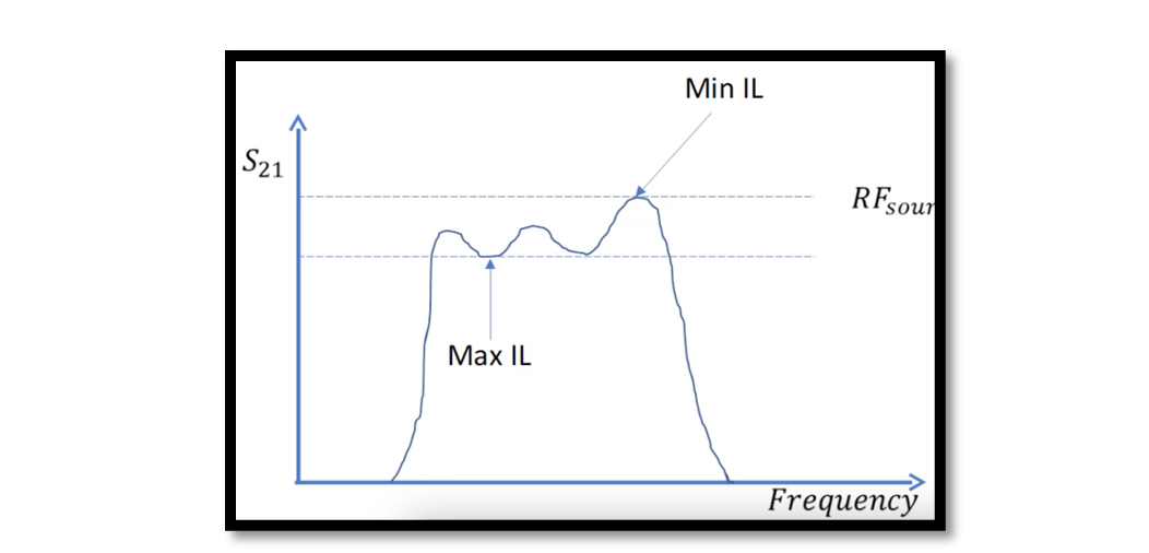
The equation for passband ripple is calculated by subtracting the minimum insertion loss from the maximum insertion loss over the frequency range of interest. The measurement procedure for passband ripple closely mirrors that of gain flatness, maintaining the same setup as previously discussed in our blog on gain flatness. The approach involves fixing the power level on the RF source and subsequently sweeping the frequency to measure insertion loss across the frequency band. An illustrative example of a filter response showcases characteristic ripples within the passband. The passband ripple, quantified as the difference between the maximum and minimum insertion loss, yields a positive value, providing a straightforward and intuitive measure of the ripple’s impact.

Analyzing Passband Ripple Equations and Measurement Procedures
To delve deeper into the understanding of passband ripple, let’s scrutinize the equations and measurement procedures involved. As mentioned earlier, the passband ripple equation calculates the difference between the maximum and minimum insertion loss measured across the frequency range of interest. This straightforward calculation provides a quantitative measure of the ripple effect within the passband.
The measurement procedure aligns closely with the methodology employed for gain flatness. Consistency in maintaining a fixed power level on the RF source and sweeping the frequency band ensures accurate measurement of insertion loss variations. This standardized approach facilitates a comprehensive analysis of the passband characteristics, aiding in the identification of any irregularities or ripples present.
Furthermore, the simplicity and symmetry between measuring gain flatness and passband ripple underscore the interchangeability of these measurements. Proficiency in one invariably translates to proficiency in the other. Whether assessing gain flatness or passband ripple, a solid grasp of the measurement principles ensures a robust understanding of how different components and filters perform across diverse frequency ranges.
Passband Ripple Characteristics and Implications
Passband ripple in RF filters is a critical parameter that encapsulates the variations in insertion loss within the frequency range of interest. This phenomenon is particularly pronounced in narrowband filters like Surface Acoustic Wave (SAW) and Bulk Acoustic Wave (BAW) filters, designed to operate within specific frequency bands. The passband ripple is essentially the undulating pattern observed in the filter’s response curve, indicating fluctuations in insertion loss across the passband.
Understanding the characteristics of passband ripple is crucial for engineers and designers. The ripple can be attributed to various factors such as manufacturing tolerances, component imperfections, and resonator interactions within the filter. As a result, passband ripple directly influences the filter’s performance, affecting signal quality and integrity. Engineers often aim to minimize passband ripple to enhance the overall efficiency of RF systems.
Measurement of passband ripple involves determining the maximum and minimum insertion losses over the desired frequency range. This quantification allows engineers to precisely characterize the ripple and its impact on signal transmission or reception. The obtained value, expressed in decibels (dB), serves as a crucial specification for filter performance. Notably, a higher passband ripple signifies greater insertion loss variation, potentially leading to signal degradation in specific channels.
Engineers employ various techniques to mitigate passband ripple, such as careful component selection, precision manufacturing processes, and advanced filter design methodologies. The goal is to achieve a flatter passband response, minimizing variations in insertion loss and ensuring consistent signal quality across the filter’s operating frequency range. In practical applications, an awareness of passband ripple aids in selecting the most suitable filters for specific RF systems. For instance, in communication systems, where signal integrity is paramount, filters with minimal passband ripple are preferred to maintain a stable and reliable transmission. As we delve deeper into the intricacies of passband ripple, we gain insights into its origins, its measurement, and the strategies employed to manage and optimize this critical aspect of RF filter performance.

Learn more about this topic by taking the complete course ‘Introduction to RF Testing Fundamentals and RF Test Architecture – RAHRF412’. Watch the course videos for more detailed understanding. Also checkout other courses on RF system and IC design on https://rahsoft.com/courses/. Rahsoft also provides a certificate on Radio Frequency. All the courses offer step by step approach.


