What is Lumped Circuit Analysis?
What is Lumped Circuits?
Lumped Circuit Analysis represents a foundational approach in the field of electronic circuit design, premised on the Lumped Element Model. This model simplifies the complex reality of electronic circuits by assuming that key characteristics such as resistance, capacitance, inductance, and gain are localized within idealized electrical components like resistors, capacitors, and inductors. Lumped analysis stands as a critical concept that must be grasped prior to venturing into the design of microwave circuits. But what exactly is lumped analysis? It is a prevalent method employed in analog design, where the focus predominantly lies on voltage and current measurements, rather than on power. The Lumped Element Model facilitates this approach by aggregating the circuit’s attributes into simplified, ideal components.
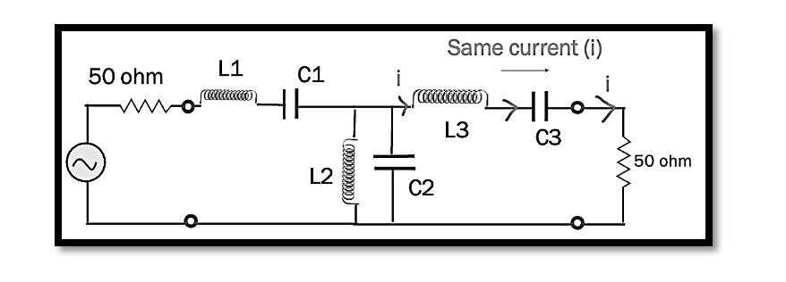
The below illustration will show what is the lumped analysis. It shows an inductor connected to the resistor. So according to lump analysis, we can say that the current passing through these two components in series is constant (Kirchhoff’s law), i1=i2=i3, so this is lumped analysis we have idealized electrical components like L R C.

Simplifying Circuit Analysis with Lumped Elements
Lumped circuit analysis is grounded in the principle that a circuit, in its most simplified form, consists solely of distinct lumped elements like resistors, capacitors, and inductors. This approach assumes the circuit to be ideal, focusing exclusively on these discrete components and modeling their behaviors through parameters such as resistance, capacitance, and inductance. To better grasp this concept, let’s visualize a generic circuit composed of various nodes interconnected by lumped components, such as resistors, inductors, and capacitors.
In such a simplified model, we apply fundamental circuit analysis techniques like Kirchhoff’s Voltage Law (KVL) and Kirchhoff’s Current Law (KCL) to determine the voltage at each node and the current in every branch. This method permits us to overlook more complex phenomena, concentrating instead on the basic interactions at nodes and between components. By treating the connecting wires between components as ideal (having no impedance or delay), we allow for a straightforward analysis, greatly simplifying the process of understanding circuit behavior.
When engaging in lumped analysis, we essentially ignore the physical distances between components, operating under the assumption that these are negligible and that the components are closely integrated. This assumption is valid for many practical applications, where the distances between components do not significantly affect the circuit’s overall performance. The utility of lumped analysis spans across various types of circuits, enabling the application of KVL and KCL to simplify and solve complex circuit problems efficiently.
Understanding Lumped Analysis Through Circuit Simplifications
Lumped analysis operates under the foundational premise that the physical dimensions of a circuit are sufficiently small relative to the wavelengths of interest, ensuring that the voltage across and the current through the conductors connecting elements are essentially uniform. This approach hinges on a critical simplification: in a two-terminal lumped circuit element, the current entering is exactly the same as the current exiting, disregarding any phase changes or transient effects that are considered negligible.
To illustrate, consider an image depicting a circuit composed of an inductor and a capacitor, emblematic of lumped element analysis. According to Kirchhoff’s current law, the current entering a branch is equal to the current exiting, as visually represented by arrows indicating the direction of current flow. This uniformity underscores the lumped analysis principle where the proximity of components ensures minimal variation in current through any two-terminal device.

Lumped-Element Circuit
The concept of a two-terminal lumped circuit element can be visualized by focusing on an inductor through which a constant current ‘I’ flows. The assumption here is that the physical size of this inductor is negligibly small, ensuring that the outgoing current mirrors the incoming current perfectly, without any phase shift or delay. This idealization allows for straightforward application of Kirchhoff’s voltage law (KVL) and Kirchhoff’s current law (KCL) to analyze the circuit without the need to consider distributed effects or complex electromagnetic phenomena.
Thus, lumped analysis simplifies circuit design and analysis by abstracting away the complexities of electromagnetic interactions over physical distances, focusing solely on the interaction of idealized components within a compact space. This method is particularly effective in low-frequency applications where the assumption of uniform current and voltage distribution holds true, allowing for efficient and accurate circuit analysis and design.
Conclusion:
Lumped analysis offers a streamlined and effective method for understanding and designing electronic circuits, particularly in contexts where high precision over small scales is required. By treating circuit components like resistors, capacitors, and inductors as ideal entities with concentrated parameters, this approach allows us to sidestep the complexities of varying current and voltage across physical distances. It relies on the assumption that all relevant electrical behaviors can be captured by focusing solely on the interactions among discrete elements within a compact arrangement. Through the application of basic principles such as Kirchhoff’s voltage and current laws, lumped analysis simplifies the process of analyzing circuits, making it an indispensable tool in the early stages of circuit design and for low-frequency applications.

Learn more about this topic by taking the complete course ‘Introduction to RF Testing Fundamentals and RF Test Architecture – RAHRF412’. Watch the course videos for more detailed understanding. Also checkout other courses on RF system and IC design on https://rahsoft.com/courses/. Rahsoft also provides a certificate on Radio Frequency. All the courses offer step by step approach.


