Example: Calculating Transducer Power Gain
Introduction to Transducer Power Gain
Transducer power gain (GT) is a crucial parameter in electrical engineering, particularly in the analysis of signal processing circuits and systems. It quantifies the efficiency with which a transducer, such as a sensor or a circuit element, converts input power to output power. In essence, it measures the amplification or attenuation of power within the system.
Understanding the Calculation
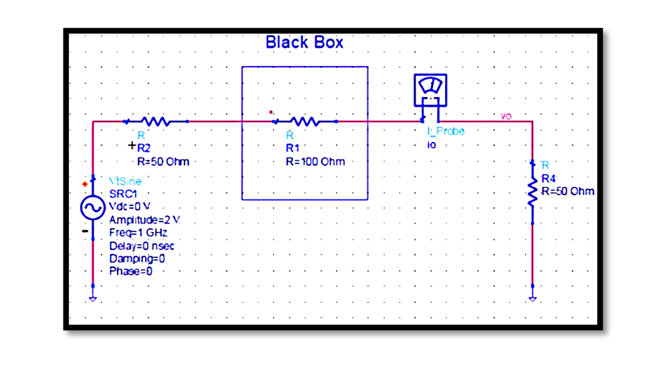
In this blog post, we’ll delve into the detailed calculation of transducer power gain using a circuit simulation tool like ADS (Advanced Design System). Our circuit setup comprises a 2-port network represented by a black box. It’s important to note that while we commonly associate power gain with amplifiers, in this scenario, our 2-port network consists of a single resistor, emphasizing the versatility of power gain calculations across various circuit configurations.
In this example we will:
- Calculate Transducer Power Gain (GT) and compare with S21
- The Black Box is the 2-port network
- Here, 2-port network is not an amplifier but a single resistor

Step-by-Step Calculation:
- Input Voltage (Vin): We begin by determining the input voltage (Vin), which is half of the source voltage (Vs) as per the given condition.
- Input Power (Pin): Using the formula for input power, where Rin represents the input resistance, we calculate the power absorbed by the network from the source.
- Output Power (PL): With the output voltage (Vo) and load resistance (RL) provided, we utilize the formula for power dissipation in a resistor to compute the power delivered to the load.
- Transducer Power Gain (GT): Finally, we calculate the transducer power gain (GT) by dividing the output power (PL) by the input power (Pin). This ratio provides insight into the efficiency of power transfer within the system, highlighting the amplification or attenuation of the input power.


Simulation

In the context of the simulation in ADS (Advanced Design System), PL represents the output power dissipated in the load. The equation EqnPL=0.5×real(vo×conj(io.i)) is used to calculate this output power.
Here’s a breakdown of the components of the equation:
- vo represents the output voltage.
- io.i represents the complex conjugate of the output current.
The multiplication of vo and the complex conjugate of io.i represents the complex power absorbed by the load. Taking the real part of this complex power gives the actual power dissipated in the load.
Now, looking at the simulation results in the table:
- Freq: The frequency column indicates the frequency at which the simulation was performed. In this case, it shows two rows: 0.00000 Hz and 1.0000 GHz, indicating a DC (direct current) analysis and a high-frequency analysis at 1 GHz, respectively.
- PL: The PL column indicates the corresponding output power dissipated in the load at each frequency. The values are given as 0.0000 and 0.0025, where the unit is not explicitly mentioned but it is understood to be in watts (W). Hence, PL=0.0025 W = 2.5 mW.
Therefore, in the context of this simulation in ADS, PL represents the output power dissipated in the load, which is calculated to be 2.5 mW. This value is crucial for further analysis, such as calculating the transducer power gain (GT).

In the context of the S-parameters in microwave engineering, S21 represents the forward transmission parameter, which characterizes the transmission of power from port 1 to port 2 in a two-port network.
- The magnitude of S21, denoted as ∣S21∣, indicates the amplitude attenuation or amplification of the signal.
- In your simulation results:
- Freq: The frequency column indicates the frequency at which the simulation was performed, which is 1.000 GHz.
- S(2,1): This column represents the S-parameter S21, which is given as 0.500/0.000.
- The first value, 0.500, corresponds to the magnitude of S21, denoted as ∣S21∣.
- The second value, 0.000, typically represents the phase angle of S21, but in this case, it seems to be absent or zero.
- ∣S21∣=0.500
To calculate the transducer power gain (GT) from ∣S21∣, the following formula is often used:
GT=∣S21∣2
Substituting the given value:GT=(0.500)2=0.25
Therefore, the transducer power gain (GT) is calculated to be 0.25. This value quantifies the efficiency of power transfer from the input to the output port of the two-port network at the specified frequency of 1.000 GHz.
Conclusion
In conclusion, understanding and calculating transducer power gain (GT) is pivotal in assessing the efficiency of power transfer within electrical circuits and systems. By delving into the intricate details of input power, output power, and S-parameters, engineers gain invaluable insights into the performance characteristics of the system. Through meticulous analysis using simulation tools like ADS (Advanced Design System), one can decipher the nuances of power amplification or attenuation, enabling informed decision-making in circuit design and optimization. From comprehending the intricacies of input voltage and power dissipation to interpreting S-parameter data, each aspect contributes to understanding of transducer power gain.

Learn more about this topic by taking the complete course ‘Microwave Amplifier and Low Noise Amplifier (LNA) Design Theory and Principles online course – RAHRF526’. Watch the course videos for more detailed understanding. Also checkout other courses on RF system and IC design on https://rahsoft.com/courses/. Rahsoft also provides a certificate on Radio Frequency. All the courses offer step by step approach.


