Intermodulation Explained with Examples
Intermodulation products are unwanted signals. They leak into other channels and creates distortion. As we discussed, not all the components cause problems, and most of them can be ignored and filtered out as the amplitude of harmonics decreases as the order increases in a non-linear system. Very high-order harmonics are ignored. The high-frequency components are often suppressed as they are quite far from the system bandwidths or don’t fall within the band pass filter limits. However, the very close components to the fundamental desired signal bandwidth are difficult to filter out. It acts as the blocker, as discussed before. As we have seen in the spectrum in previous sections, the high-order harmonics and intermodulation components are attenuated; however, the blocker remains.
As read in the introduction to intermodulation, the blocker that we get within the output of the desired signal is called the intermodulation component with amplitude 3/4a3A3
This blocker is called the intermodulation component, IM3, which is the third-order intermodulation component. IM3 shows the linearity of the system; it is the ratio of intermodulation component to the output amplitude of interferer, expressed as: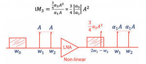
If the system is linear, then a3=0, and therefore IM3 is less. If the system has high IM3, then it is non-linear. The below figure has two slopes. One of the slopes shows the output of interferer at frequency w1 and w2 expressed in the log domain. The second slope shows the amplitude of the intermodulation component at frequency 2w1–w2.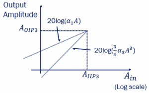 When A is small, amplitude 3/4a3A3 becomes 0. The same can be seen with the second slope, it is approaching 0 with low amplitude. When the amplitude of the interferer increases, the amplitude of the intermodulation component reaches the amplitude of the output interferer. The point of intersection is called AIIP3. This AIIP3 shows the linearity of the system, and the aim is to increase the AIIP3. This parameter is used to measure the non-linearity of our system. Higher AIIP3 means better linearity. If AIIP3 is low, then the interferers act as a blocker to our system.
The third-order intermodulation components are difficult to filter and become a complication. The amplitude of the interferer increases much more quickly than the desired signal. For every 1 dB increase of the desired frequency, the unwanted interferer increased by 3dB. As shown in the graph, theoretically, the two lines meet at a point, that is, at some input amplitude, both would match. The point at which the slopes meet is called the third-order intercept point. AIIP3 is the input third-order intercept point, this point is theoretically calculated based on the measured values, and it provides the measure of non-linearity of a system. To measure the extent of linearity in a system, a third-order intercept AIIP3 is used. The point at which the blocker signal gets really high with AIIP3, equalizing the two outputs as shown below, we can get the AIIP3value. A-1dB had a similar formula that was discussed in the section Gain Compression; therefore, the relationship between AIIP3 and A-1dB can be expressed: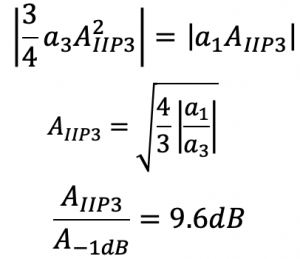
We can say that the compression point A-1dB and AIIP3 both shows the non-linearity of the system. Calculating these will provide us the measure of non-linearity in a system.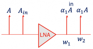
Take an example of LNA with two interferers, where ‘Aout, int(w1,w2)’ is the output from LNA and Aout(IM3) is the intermodulation component. The a1Ain,int is the input amplitude of our blocker interferer, and as it is in the output, it is multiplied by gain a1. Therefore, AIIP3 for this LNA can be calculated using the below formula. The diagram shows two interferers closely spaced signals as inputs with the same amplitude. The equation uses the difference in power of the fundamental and the IM3 components (delta P/2) to calculate the third-order intercept.
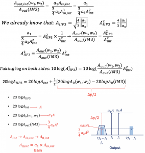
If we know the input amplitude of the interferer, the output amplitude of interferer in frequency w1 and w2, the gain of the system, and the blocker signal amplitude inside the desired channel, then with the above equation, we can find the AIIP3.
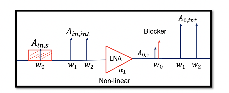
Example 1: We have a non-linear LNA system, w0 is the desired signal with amplitude Ain,s, and we have two interferers w1 and w2 with high amplitude Ain,int on the input end.
Now when these inputs are fed to the LNA, we get many components on the output end. Shown are four components that we are concerned about. The rest of the components can be ignored, as discussed before. On the output A0IM3 is the blocker, which falls within the desired signal band. A0,int is amplified output interferers. The given value for AIIP3 is -10dBm, which is converted to voltage 70mv. We need to find the ratio of the output signal and IM3 or say the difference between these two signals in the log domain. The ratio calculated is 4.9, which means our signal is higher than the blocker.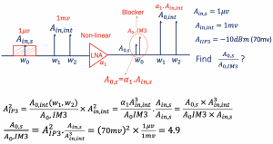
Example 2: This example is from RF Microelectronics 2nd edition B.Razavi P.87
Consider the scenario shown in the below figure, where w3–w2 = w2–w3 and the bandpass filter provide attenuation of 17dB at w2 and 37dB at w3. Compute the IIP3 of the amplifier such that the intermodulation product falling at w1 is 20dB below the desired signal.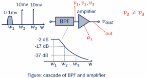
Shown in the question is the transfer function of the bandpass filter representing the amplitude and frequency. Practically we cannot have a filter with 0dB loss, and there will be some loss associated. As shown here, -2dB which is almost negligible. w1 is at -17dB and w2 is -37dB.
In this example, there is a bandpass filter before the input goes into the amplifier. The aim of using a filter is to attenuate the two interferers. w1 is the desired signal, and w2 and w3 are the interferers with high amplitude. Using a filter will attenuate as much as it can. As we know, the amplifier is non-linear, and sending a signal without using the filter, interferer signals will directly go into the amplifier. The very high amplitude of the intermodulation component will appear in the desired channel and block the signal. The intermodulation product is the blocker that appears inside the desired channel.
The question asked here is, if we have an output signal with blocker, then calculate the AIIP3 in a condition such that the difference of output signal and blocker is 20dB. If the difference is 20dB, then the blocker will not block the desired signal.
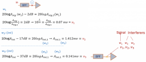
The desired signal is V1, and the interferers are V2 and V3. Now we need to find the output, where a1 is the gain of the amplifier. Due to filter response, the amplitude of interferers may not be equal; V2 is not equal to V3. Therefore, the equation can be written as: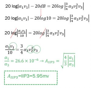
Substituting the values of V1, V2, and V3 to find the ratio of a1 & a3, we get 26.6 * 10-6. Therefore, AIIP3 calculated will be 5.95mv. So, the amplifier has to be designed so that it has AIIP3 of 5 or 6mv which is acceptable, to reduce the power of intermodulation product to neglect its effect within the desired signal for a non-linear system.
Example 3: In this example, we need to find the intermodulation component IM3 and the amplitude of intermodulation component A0(IM3).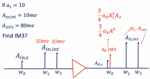
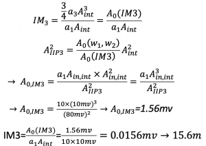
We know IM3 is the ratio of the intermodulation component amplitude and the amplitude of interferer at the frequency of w1 and w2. If we have two closely spaced interferer signals as input to a non-linear signal, then in output, we get a blocker within the desired signal along with two interferer components at w1 and w2. Intermodulation component IM3 calculated is 15.6m.


