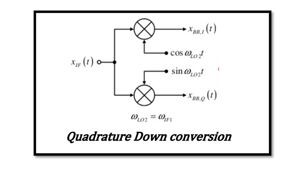
Understanding Quadrature Down conversion
Quadrature down conversion
The quadrature signals are used in order to solve the image problem that we faced in the zero-IF receiver. In quarter down conversion, we create two versions of the down converter signal with a phase difference of 90 degrees. So basically, we are creating quadrature signals. As we have done in previous sections, the 90-degree phase shift and reached other signals, a similar thing is done in down conversion to remove the problem.
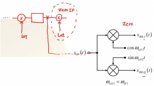
When we look back to the structure of the dual converter receiver, we have a mixer with WLO1 for first down conversion, then comes a filter, amplifier, and a second mixer with WLO2 where we face the problem related to Zero IF for the secondary image.
So introducing the new structure called the quadrature downconverter, as shown below, will solve our problem. This quadrature down conversion uses two mixers, one fed with a cosine wave and the other with sine wave. So the same IF data will go to two different paths in order to be created in order to be changed to quadrature signals. These signals are in baseband, hence denoted by BB. So, for example, XBB, I(t), and XBB, Q(t) are called the ‘’quadrature baseband signals’’. This is the first method to produce these signals.
There is another other method to produce these quadrature signals. So instead of using two different waves for mixing, we can give only the cosine wave for two mixers, and phase shift our data; however, the first method is preferred over this method of down conversion because having the 90-degree phase shift on data for baseband signal is challenging.

The in-phase spectrum XBB,I(t)
Let see how using these two mixers, and we can solve the previous image problem. XBB,I(t) is the in-phase spectrum and XBB,Q(t) is the Quadrature spectrum.
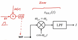
The first part of our data is multiplied by the cosine wave and the second part with sine wave. In the first mixer, we have WIF, so assuming we have a dual IF receiver here, the first mixer in the dual receiver is fed with RF, and then it is mixed with WLO1. After filtering and amplification, we reach intermediate frequency. So now the channel is an intermediate frequency, and we can do the down-conversion.
The channel here is asymmetric, that is FM modulation. So after mixing with Cos WLOt we see the result: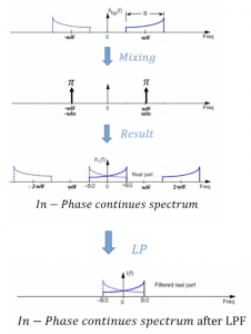
We need to mention the frequency of the local oscillator here as we want this part to be a zero-IF. The local oscillator frequency is equal to center frequency of our channel (WIF). Now we are able to down-convert our signal to a baseband that is around 0 frequency. We get four components, the low pass filter at the end will filter out the higher frequencies. It can be noticed that the baseband data is asymmetric data, but the total shape of data will become symmetric, and it will corrupt the shape of data. However, we want to get the output shape of the channel asymmetric; hence, after filtering, we have XBB, I(t) it means baseband around the 0 frequency, and ‘I’ means in-phase continuous spectrum after filtering in the frequency domain.
The Quadrature spectrum XBB, Q(t)
The second part of our data is multiplied by sine wave. Thus, XBB, Q(t) is the Quadrature spectrum.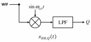 The second half of the structure is where the data is then multiplied by a sine wave. The channel is in intermediate frequency, and we can do the down-conversion, and after mixing with Sin WLOt we See the result as:
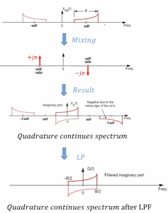
Our data here becomes negative and also imaginary because we multiplied it by j. So this spectrum is called continuous quadrature spectrum, XBB, Q(t), BB refers to baseband, and ‘Q’ means quadrature. So again, we get four components, and then the low pass filter removes the higher frequencies resulting in a continuous quadrature spectrum in the frequency domain.
As we can see, these two shapes from XBB, I(t) and XBB, Q(t), are not enough because we still have a problem with our data.
How to reconstruct the original data?
As shown in the below figure, we have two parts the first one is the front end, and the second one is the signal processing.
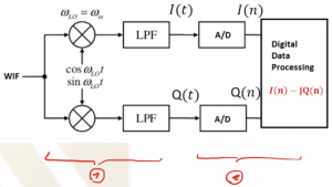
We have our I(t) and Q(t) as shown in the below figure and doing some modification here that is to multiply Q(t) with -j and then adding the two signals we get I(t) – jQ(t). All this takes place in the digital domain. So using this process, we can restore the shape of our data. This is the purpose of using the quadrature down conversion. So if we get I(t) and Q(t) and doing digital signal processing, we can get I(n), and for Q(n) we multiply by -j then add these two together to restore our signal.
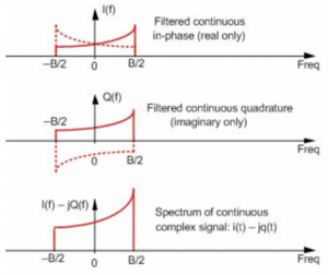
This process can be shown using a three-dimensional view with the frequency with real and imaginary parts for better understanding.
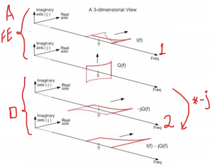
As it is a spectrum, we are referring to it as I(f). In the real axis, we can see we received two kinds of channels, one shown with dotted lines. The channel has become its own image which is the problem that we need to address, and we can see it here.
We have multiplied the data by J in the imaginary axis Q(f), so it’s a completely imaginary part. Let’s see what is happening to these signals when we do the process. The first part is actually the analog that is the front-end, and the second part is digital. In signal processing, first, we multiplied Q(f) with -j. When we multiplied Q(f) by -j, it was imaginary, and now it becomes real. So Q(f) becomes real in digital signal processing and now adding the two signals (1&2) together, the dotted part, which is the image channel, gets cancelled out, and we will restore our channel. This is the purpose of using this kind of structure as, in the end, we are able to restore our data and solve the problem where the signal becomes its own image.


