Drawbacks of Weaver Architecture
Drawbacks of Weaver Architecture
The previous blog discussed about the weaver architecture for image rejection. Like Hartley receiver, weaver architecture also has some drawbacks.
- Secondary image
- Mixing Spurs
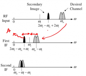
The first drawback is the secondary image if the second IF is not zero. The problem is the secondary image as it’s not zero IF. If we are not using zero IF for the second part if we don’t use a second IF will have a secondary image. As you see in the diagram below, after the first down conversion here we have something like this:
Look at the signal at point A: if we have such a signal which is called the second image at point A, the difference between this signal to w2 is equal to the difference between w2 and the down-converted channel, so basically it will be translated to the second wIF. So this is one of the problems. It mainly depends on our application, if there is a second image we have to use zero IF for this structure, which is a bit different and we will explain it in the blog.
The second drawback is Mixing Spurs. If there are two mixer stages then there will be mixing spurs.
Double Quadrature Down Conversion
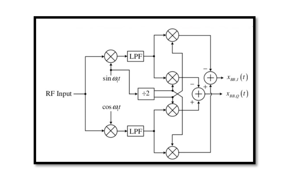
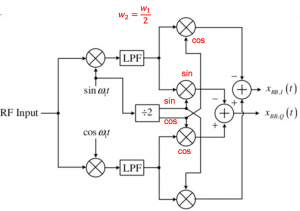
This structure is used for the zero IF, called double quadrature down conversion. It is actually a sliding receiver. What are sliding IF receivers? In reality, we cannot use local oscillators in one receiver structure, as oscillators fabricated on one chip suffers from unwanted coupling creating more problems. Therefore, only one oscillator is employed that is used to produce the required frequencies. This type of receiver is called a sliding IF receiver.
This structure has a frequency divider (÷2) so, w2=w1÷2 and we do have a 90-degree phase shift as well here so which means that we are actually producing sine and cosine.
Why there are four mixers used in order to have zero second IF?
If you see the below is weaver structure. Look at the second stage, we said w2=w1÷2 and we will have zero IF at the output of this receiver, discussed in the previous blog when explaining this structure. However, we cannot use this structure for zero IF because for the second part the signal becomes its own image.

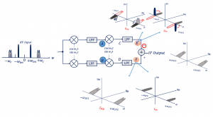
If at all we use this structure for zero if. For zero IF wIF2 = 0, this signal will come to the baseband. There is no problem if the channel is symmetrical as in this case but for some modulations, we don’t have symmetrical channels and the down-conversion will corrupt the signal, and we have the same problem we explained before, the signal becomes its own image and if you have asymmetrical channel we will have a problem in down conversion because basically, the shape of our signal is changed when its translated to baseband.
Going back to the double quadrature down conversion- so what happens is we are separating the parts producing in-phase and quadrature, doing it for each part to avoid having the image. Using digital signal processing the data can be easily restored.


