Dual-Band Receiver with Example
Structure of a Dual-Band Receiver
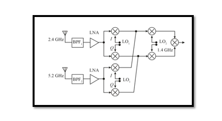
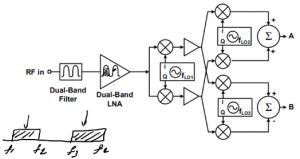
The structure shown below is a very interesting structure called the Dual Band receiver which has a dual-band filter and dual-band LNA. It means the filter has two bands, f1 to f2 and f3 to f4. The LNA is tuned to receive two bands, so it’s amplifying the two bands. We will explain how this structure works for two bands using an example:
Before we go to the example, let’s talk about this receiver. We have two signals here two bands, the first is the 2.4GHz and the second one is 5.2GHz and these are actually an image of each other. So we can say that one is the high side and the other is the low side for this example. The question is are we getting these signals at the same time? The answer is no. If both the signals operate at the same time then they will be in the same baseband hence interference would occur. Imagine this more like a switch, so each time these band gets switched.
For the 2.4GHz band: 3.8GHz – 2.4GHz -1.4GHz = 0 (baseband)
For the 5.2GHz band: 5.2GHz – 2.4GHz -1.4GHz = 0 (baseband)
This is the actual image rejection, the weaver structure as we discussed previously. So this is how this receiver works now we can do an example. In a previous blog, we talked about weaver architecture and its drawbacks.
Example of Dual Band Receiver
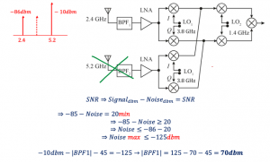
The receiver operates at 2.4GHz and receives 85dBm. Receiving interferer -10dBm in 5.2GHz. Find the amount of rejection in BPF1 in order to have SNR =20dB. The IRR=45dB.
SNR-> Signal-to-Noise ratio
IRR-> Image Rejection Ratio
If the receiver operates in 2.4GHz it means that the second part 5.2GHz is switched off or disabled. At the input of this receiver, we have a 2.4GHz signal and high interferer which is –10dBm, and a carrier shown using the dotted arrow. These signals are the image of each other. We need to reject the image -10dBm that is at 5.2GHz. So the goal is to find the amount of rejection in bandpass filter 1 (BPF1) to get rid of this problem to have an SNR of 20dB. The given image rejection ratio is 45dB.
Therefore, we have reached to 70dBm which is the amount of attenuation. Additional attenuation from the bandpass filter is needed, without it, our system will not be able to reach the required SNR with only the image rejection ratio. As IRR is not enough, we need to have the BPF. So in this example with this interferer -10dBm the attenuation should be at least 70dBm, if you have more attenuation you can reject more and achieve more SNR.


