Introduction to Transmitters
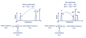
In this blog section, we will talk about transmitters and their different architectures. We have now finished our receiver blogs check them out RF system design of Receivers. We will be introducing the main blocks of the transmitter, Let’s start with an introduction to up-conversion. Imagine we have IF data, which is modulated data, by doing up conversion we are trying to shift this channel to higher frequencies, for example, we can use a local oscillator and multiply by cosine and we will have two channels around the local oscillator as shown in the below diagram. The frequency of data is shifted from intermediate or low frequency to high frequency. So we can say that modulated is translated to high frequency.
Comparison between upconversion and downconversion
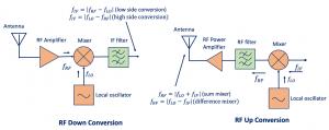
In simple words, most of the transmitter architectures are similar to the receiver topologies but with the operations performed in reverse order.
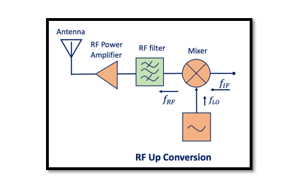
In the receiver we had a heterodyne system (RF to IF), so we have different structures the operations are performed in reverse for transmitters which will be up-converting from IF to RF or let’s say baseband to RF if it is direct upconversion. So on the left side, we have the receiver structure is where we have LNA, RF signal, Mixer, LO, and IF. Here we are shifting from RF to IF or zero or baseband. But on the other side we have up-conversion, IF or baseband data using the mixer and moving towards higher frequencies, then using an RF power amplifier in order to amplify the signal as the signal experiences attenuation from the outside environment and by the time it reaches receiver the power is not strong enough, so, the power amplifier is used to increase its strength, the power depends on the application for example for Bluetooth with less distance, we don’t need to have higher power but when we have an application like mobile phones we will need higher power as the distance between the mobile phone station is more and the signal will get attenuated on the way. So, the diagram above shows the difference between up and down conversion.
What is a transmitter?
A transmitter or radio transmitter is an electronic device that generates radio waves using an antenna. A radio frequency current is applied to the antenna which in turn produces electromagnetic waves. A transmitter can either be a separate unit or an integrated circuit (IC) within another electronic device.
Transmitter Blocks

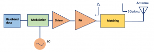
Starting with the Baseband block, this can be a digital part, generally these days it is digital, we use ADC to change it to analog or sometimes we have digital modulation or analog modulation. So, first, we have the data, and this data can be in a baseband, it has a low frequency, and we will be doing modulation, it can be QPSK or FSK or maybe analog modulation. For this modulation, we will need a Local Oscillator (LO), the carrier frequency.
So first we are doing modulation and at the same time doing the frequency shift, so shifting the baseband band data from low frequency to high frequency so it’s all happening at once. This can however be a separate process as well; we can say the modulation increases the frequency of baseband data a bit to the IF and then we can use another mixer and translate data to RF frequency.
The driver and PA are the amplifiers, the driver is a part of the power amplifier we use this block to drive the power amplifier sometimes using one stage of PA is not enough, and might need another stage in order to increase our gain and drive this part. Altogether this block is to increase the power of our signal that we discussed in the above paragraphs. The matching circuits have two kinds of jobs. The first one is we know that the output impedance of this antenna is 50ohms but on the other part, we have ZL the impedance at the output of the PA. To have the proper operation, should be a specific impedance at the output of this PA in order to have the desired power and power efficiency, which means we won’t have 50ohms and we need to design a matching circuit to match it to 50ohms without the loss of power. So we are actually transferring the maximum power from the output of PA to this antenna and it is going to be radiated. The matching circuit acts as a filter and filters the unwanted signal.
How does the matching circuit act as a filter? For example, let’s say we have narrowband modulation and sending data in frequency 2.4 GHz, it can be AM modulation. In AM modulation the frequency is not changing we have a fixed frequency, because the system blocks are non-linear, at the output we will have 4.8 GHz or maybe 9.6 GHz as a second and third harmonic, so this matching circuit acting as a filter will attenuate these harmonics and we will be able to get the fundamental frequency from the output of our transmitter.


