Demystifying Error Vector Magnitude (EVM)
Have you ever imagined of a single parameter that entirely captures the performance of your RF line-up? Yes, Error Vactor Magnitude (EVM) is such a powerful metric that it encapsulates the information regarding system linearity, noise floor, and phase-noise simultaneously. Therefore, while designing and debugging your RF line-up, EVM measurements can provide significant insights as almost all types of error-sources (harmonic distortion, compression, Noise floor, phase-noise etc.) translates to measurable EVM.
What is EVM?
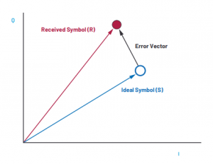
EVM is a simple metric to capture quick insight into overall system performance and is usually used for communication systems involving digital modulations. Qualitatively speaking, it is the distance between received symbol position and ideal symbol position, in a constellation diagram. So essentially, EVM measures the displacement of a symbol from its ideal position on constellation diagram, and this displacement can be caused by several system-level impairments including non-linearities, harmonic distortion, noise figure, phase noise etc.

What influences EVM?
In the following, we will briefly discuss what error-sources in a communication system affect EVM.
(a) White Noise and EVM: White noise is present in all communication systems. Since white-noise affects system’s SNR, EVM can be expressed in terms of SNR as follows:
EVMWN = -SNR + PAPR +3
where SNR is the Signal-to-noise ratio of System in dB and PAPR is peak-to-average-power ratio of signal in dB. Note that PAPR is related to modulated signals.
For high-speed ADCs and DACs, above formula can be expressed in terms of Noise-Spectral-Density (NSD):
EVMWN = NSD + 10logBW + PAPR + Pbackoff + 3
where NSD is Noise-Spectral-Density of converter in dBFS/Hz, BW is signal bandwidth in Hz, PAPR is peak-to-average-power ratio of modulated signal, and Pbackoff is the difference between peak power of the signal and full-scale range of the converter. NSD of high-speed converters usually encapsulates quantization noise too along with thermal noise and so, above equation represents effects of both thermal as well as quantization noise on EVM. These two equations clearly explain that EVM is directly related to signal BW, PAPR and system thermal noise. So, wireless communication systems employ complex modulation schemes with high PAPR and high signal bandwidths in the quest of high data-rates, however, there is a trade-off too in the form of degraded EVM as we just explained!
(b) Phase-Noise and EVM: Phase-noise of a system directly impacts its EVM. Overall phase-noise is constituted by many clocking contributors in the system like sampling-clock for convertors, LO for frequency conversions and Reference clocks etc. To calculate EVM due to phase noise, we need to integrate the SSB phase-noise over signal bandwidth. Therefore, systems operating at wider signal bandwidths and high carrier frequencies, are more prone to degraded EVM due to phase noise effects. For further details on phase-noise, read here…
(c) Non-linearities and EVM:
System non-linearities produce inter-modulation products and these products can fall with signal bandwidth, especially third-order intermod products. These intermod prodcuts can interfere with carrier amplitude and phase resulting in EVM distortion. A mathematical formula to estimate the EVM due to third-order products is presented below:
EVMlinearity = 2Prms – 2OIP3 + C,
where Prms is rms average of the signal, OIP3 is the output third order intercept of the system, and C is constant that ranges from 0 to 3 dB depending upon modulation scheme. It can be clearly observed that EVM increases if OIP3 is reduced, and EVM improves with reducing Prms as lower signal power reduces the power-level of intermod products.
Optimizing system performance using EVM
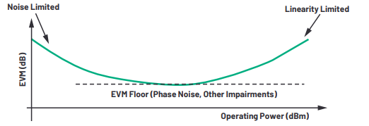
System-level performance can be optimized using EVM bath-tub curve. In the following, EVM vs. system operating power graph is shown. At lower operating power levels, EVM is dominated by noise floor, whereas at high power levels, EVM is controlled by system non-linearities. It can be observed from the following bath-tub curve that lowest EVM floor is governed by all system parameters including non-linearities, noise floor and phase-noise. So, EVM is such an instrumental tool which can be used to optimize all important parameters simultaneously!


Learn more about this topic by taking the complete course ‘RF System Design of Receivers, Transmitters & Transceivers – RAHRF409’. Watch the course videos for more detailed understanding. Also checkout other courses on RF system and IC design on https://rahsoft.com/courses/. Rahsoft also provides a certificate on Radio Frequency. All the courses offer step by step approach.
Tag:EVM
