What is Carrier Leakage?
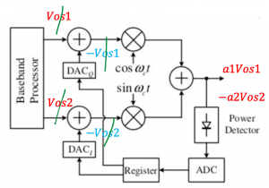
This blog talks about the carrier leakage within the transmitter. The analog base circuitry producing the quadrature signals in a transmitter exhibits DC offset. What is DC offset? DC offset is coming from local oscillator leakage. The local oscillator leakage problem causes large DC offset in the baseband and saturates the baseband circuits. Read more about DC offset with example. There are two total DC offsets; Vos1 and Vos2, they are two DC offsets referred to as the input port of the mixer, we can show this using the diagram below:
Now because of the analog circuit at the baseband part and the mixer, we have DC offset. We can refer to this offset as the input of the mixer, so now there is DC voltage here. Adding this DC voltage we will be seeing the effect of it. At the output, we have the term with GMSK and two unwanted signals, which is one of the problems and we can show the measure which is called the relative carrier leakage:
What are the problems caused by carrier leakage?
- Leakage distorts the signal constellation.
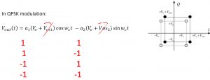
Let’s imagine the QPSK modulation below:
a1 and a2 values are as given below (11, -11,1-1,-1-1), so here we are multiplying by the amplitude of cosine and sine but also this time adding something else. This offset will change the constellation because we have extra terms and it will change/distort the signal.
This will change the constellation as we were supposed to have these values a1Vo and a2Vo and now we have extra value which also means that we have extra power, as the amplitude is increasing.
2. The base station measures the power level received from the device to adjust its transmitter power.
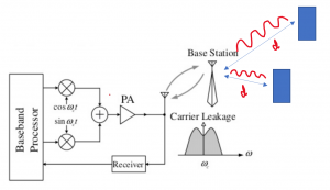
Let’s imagine that the diagram here which shows a mobile system, so in this system, we have a transmitter, for example, it’s a gmsk transceiver, so each time this transmitter sends the signal to the base station and according to the level of the power base station is just the power and transmits the power in order to communicate with this mobile. For example, there is a mobile at a far distance and another one close to the base station. When the base station receives signals from the mobile which is close by, it understands that this mobile is close, so when the base station tries to send the signal to the mobile it adjusts the signal power level according to the distance. For the mobile which is at a distance far from the base station sends the signal, the signal gets attenuated and the base station understands that the mobile is based at a far distance, hence the base station sends a strong signal as compared to the previous scenario. A low amplitude signal will get attenuated and it won’t be able to reach or get detected the mobile with acceptable SNR.
However, in presence of the carrier leakage the carrier power dominates, making it more difficult to measure the actual signal power. If you see the diagram in the previous point we have two amplitudes for cosine and sine, and it’s aVo in an ideal case but with a carrier leakage meaning extra power. The high offset value will dominate the power of the carrier so it shows that the base station won’t be able to measure the correct power because of the leakage.
How to decrease the carrier leakage?
- The carrier leakage can be decreased by designing precise circuitry.
- Also increasing the amplitude for GMSK which will decrease the value.
The aim is to always reduce relative carrier leakage measures. But there is an extent to which the amplitude can be increased as the mixer will operate in a non-linear.
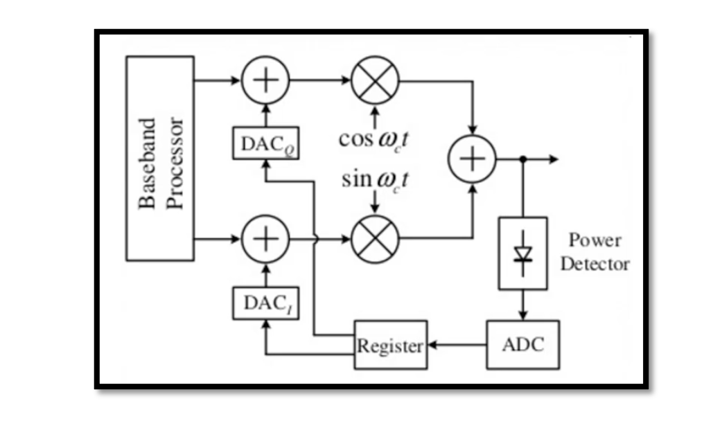
There is a better method to reduce carrier leakage. Refer to the above system diagram, it is on but we are not sending any signal we have offsets Vos1 and Vos2, which goes to the output, and here we have a power detector that measures the power of offset. Because we said we are not sending a new signal here so this power detector detects the power which is coming from the offset and digitalise it as sometimes we actually save this in memory because this offset may change depending on the operation of the transmitter so sometimes we say the values have different powers for different offsets that’s why we adjust offsets and is not always constant. So we digitise it then we will take it using the digital to analog converter (DAC). We are actually producing the offset which has a negative sign, so as you see we can cancel them here which will give us 0 offsets. This is a very good method and is commonly used.

Learn more about this topic by taking the complete course ‘RF System Design of Receivers, Transmitters & Transceivers – RAHRF409’. Watch the course videos for more detailed understanding. Also checkout other courses on RF system and IC design on https://rahsoft.com/courses/. Rahsoft also provides a certificate on Radio Frequency. All the courses offer step by step approach.


