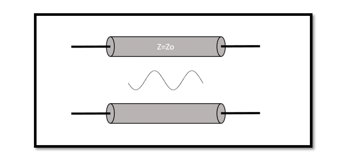
What is Transmission Lines?
RF Transmission Line
In simple words, the purpose of an RF Transmission line is to transmit RF power from one point to another efficiently. Hence, considering the best RF cable hold an important role in radio systems. The categories include cables and waveguides. In RF systems, the transmission line is the connecting link between the antenna and the transmitter that generates the power to drive this antenna.
What is a Transmission Line?
This blog will briefly talk about how we can do a distributed analysis of transmission lines. Transmission lines are not just simple connecting wires unlike lumped systems where voltage and phase are the same however it’s not the same in transmission lines. With short wavelengths, we are dealing in RF and in transmission lines, the magnitude and phase over its length vary at different points. The transmission line is a distributed network, and it has a length comparable to the wavelength. Using the image below, if we select two points on this transmission line the voltage and current will not have the same amplitude or phase. One of the best ways to analyze this system is by dividing this transmission line into an infinite number of sections.
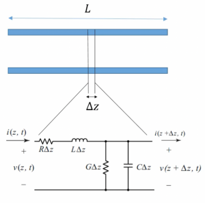
Imagine that we have a transmission line and the length is equal to L from where we select a short segment. As this is a short section it can be modeled with lumped network because we are now only talking about a small section where length might be let’s say 1m and ∆Z is 1mm which is very short compared to the wavelength. We will use some equations to solve this.
From the circuit below starting with the left side, we have resistance and then we have inductance. In high frequency even a small wire acts as inductance, it is not necessary to have spiral wires to act as inductance, in high frequency a small wire can show inductance behaviour. Then we have some resistance between the plates, G = 1/R, and capacitance as well. What is R∆Z here? R is a series resistance per unit length for both conductors in Ω/m. Simple example let’s say R is 100 Ω/m and we want to find the resistance of this small section, L=1m. In order to find the resistance here we’re going to multiply this by 1mm for this small section. So the resistance for this small section R∆Z is going to be 0.1Ω.

 The same goes for inductance, conductance, and capacitance. We have resistance in series with inductance for the top line because in high frequency it is going to act as inductance, and we have a capacitance and also resistance between two plates. This shows the capacitance between two plates. In the real world if you have two plates these two plates it’s going to act as a capacitor.
This capacitance is the capacitance between the top and bottom plate so this is how we can start analyzing our distributed network. Select a small part then write equations and at the end, we are going to say that ∆ Z is going to be zero because it’s very small then in this next blog we explain how you can write the equations, and finally, we’re going to arrive at the general equation for a transmission line using this analysis.


