Lumped Circuit Analysis Vs Distributed Analysis
In this blog, we will talk about distributed versus lumped analysis for a basic understanding of the transmission line concept, why we use transmission line, what is the lump component and why it’s a distributed element. In later parts, we will use some equations to show what happens if we load the transmission line with certain impedance and transient waves. Then see how it’s in the time domain.
What is lumped circuit analysis?
The lump element model of electronic circuits makes the simplifying assumption that the attributes of the circuit like components; resistance, capacitance inductance and gain like voltage gain, and current gain everything are concentrated into idealized electrical components joined by a network of perfectly conducting wires. When we say idealize electrical components, we’re assuming that these components are ideal components connected with wires.
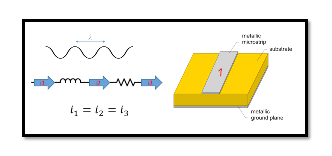
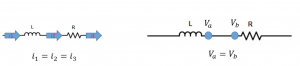
The below illustration will show what is the lumped analysis. It shows an inductor connected to the resistor. So according to lump analysis, we can say that the current passing through these two components in series is constant (Kirchhoff’s law), i1=i2=i3, so this is lumped analysis we have idealized electrical components like L R C.
Another example of lumped analysis is shown in above illustration. If we try to solve the circuit by finding the voltage at each node. The voltage at node a is equal to the voltage at node b. This is lumped analysis, where we have components, and these are connected by wires where the existence of the wires between the components is ignored. The lumped analysis is done in integrated circuits where we have small circuits. Yes, it is valid. Does the question arise as to when is lumped element model is valid? When can we do lumped analysis?
Lumped-element Model example
When is lumped element model valid?
The lumped element model is valid whenever Lc (the dimension of the component) is much less than the wavelength. Mostly the assumption is that the length should be less than 0.1 λ.
Wavelength and frequency are inversely proportional, so we have to consider that if frequency increases the wavelength (λ) is going to decrease, so we have to use smaller components. In RF circuits, wavelengths are getting much smaller, hence we can say that wavelengths are comparable with the dimension of our component.
Let’s take the same example. We can say that the wire between the resistor and inductor has a length of 1mm we can do lumped analysis if we have a wavelength of say 10mm, but what if we have a wavelength of 1mm this time we cannot do lumped analysis because as we said before Lc should be much smaller than the circuit characteristic wavelength.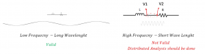
The below illustration shows on the left side is for low frequency so longer wavelengths. Let’s say we have a small circuit here so we can do lumped analysis and it’s valid because the wavelength is much longer.
On the right side we have high frequency so short wavelengths and this time as you see the wavelength is comparable with the characteristic length of our components. Therefore for the left side, the lumped analysis is valid. In integrated circuit designs for chips sometimes the length and width of the chip might be 1mm by 1mm and components within them might be much smaller than 1mm which is not even comparable with the signal with may be 10Ghz, so in this case we can do lumped analysis.
Let’s say we are designing something on the board with high frequency like on the right side where each connection between the components within the board acts like a transmission line. If you calculate voltage along the line it will not be the same, V1≠V2. So here we do distributed analysis instead of lumped analysis.
Distributed Analysis
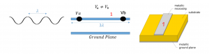
The best example for distributed analysis is transmission lines, we cannot ignore the connection that is the lines between these components because now this line is comparable to our wavelengths. As shown in the below illustration of the transmission line. The transmission line is nothing but just a wire you can assume there are two wires one is like your ground plane as you see on the right side this is simple examples of microstrip transmission so as you see this rectangle the first wire let’s say 1 is the top plate and there is the ground plane on the other side of your substrate this is two metal layers. This is making your transmission line so here, for example, we are showing the lengths of transmission lines as 3 λ but the wavelength is λ so much higher so we can assume this is a distributed analysis because of the longer length. Even if the length is λ /4 distributed analysts should be employed.
Approximately the length should be less than 10 λ so even if your length is like λ / 4 again you cannot do lumped analysts you just have to do distributed analysis. For example, we have two voltages here and an incident wave going into this wire. This time Va ≠ Vb. In the next blog we’re going to explain why this happens.

Learn more about this topic by taking the complete course ‘RF Microwave and Radio Frequency Transmission Theory Online Course – RAHRF200’. Watch the course videos for more detailed understanding. Also checkout other courses on RF system and IC design on https://rahsoft.com/courses/. Rahsoft also provides a certificate on Radio Frequency. All the courses offer step by step approach.
You may also like
Understanding Quadrature Amplitude Modulation (QAM) and Its Applications