Transmission Line Phasor equations
In the previous blog what is transmission line, we discussed that we are dividing a transmission line into many incremental segments and assuming each segment is lumped network because of its short length.
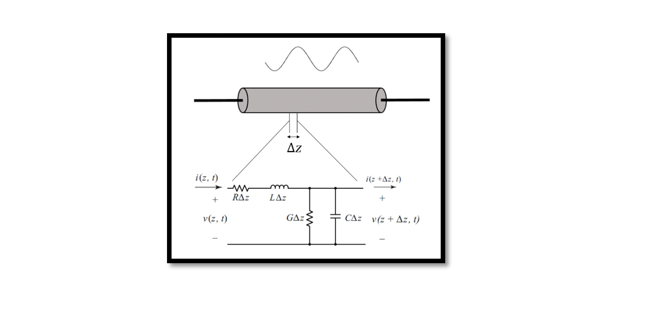
In this blog, we will talk about the equations and derive them. Also, obtain the current and voltage phasor equations for the transmission line. We have a short segment as shown below, where the length is ∆Z, hence the start and end of this segment become Z and Z+∆Z respectively.
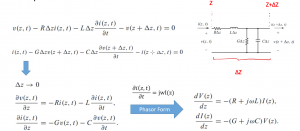
The voltage and current here are like the function of time and location. So we’re going to have two voltages here; the voltage at the input of this network and output of this network, they are at different locations; one is V(Z,t) and the other one is V(Z+∆Z). The same goes for current, we have four components here, resistance, inductance, conductance, and capacitance. We can write two equations KVL and KCL. As this is a lumped analysis we can do KVL. The equations are as follows.
To solve these two equations we divide these two by ∆Z and take a limit of ∆Z as 0, as ∆Z is short length, so now we reached two differential equations. We are going to solve them instead of going to the time domain, we will change it to phasor form so basically the Fourier domain.
—
Example to show how to write equation in Phasor form:
How to write phasor form for the voltage V=2 cos (wt+30˚)?
To write the phasor form of the voltage V=2cos(wt+30˚), we need to express it as a complex exponential in the form of V = Re{V0+exp(jwt)}, where V0+ is the phasor amplitude of the voltage.
We can do this by using the Euler’s formula, which states that:
cos(x) = (e^(jx) + e^(-jx))/2
Therefore, we can write:
V = 2cos(wt+30˚) V = 2((e^(j(wt+30˚)) + e^(-j(wt+30˚)))/2) V = e^(j30˚)*(e^(jwt) + e^(-jwt))
Thus, the phasor form of V is:
V0+ = 2 ej30˚ where 2 is the amplitude and 30˚ is the phase.
where V0+ is the phasor amplitude of the voltage and is equal to 2e^(j30˚). The angle 30˚ represents the phase angle between the voltage waveform and the reference axis.
So, the phasor form of V=2cos(wt+30˚) is:
V = Re{V0+exp(jwt)} = Re{2e^(j30˚)exp(jwt)} = 2cos(wt+30˚) + j2sin(wt+30˚)
—
So going back, what we get for the derivative ∂i(z,t)/∂t is jwI(z) which is the phasor. Using this now we get the phasor form equations. Now we can write the second-order equations where gamma (¥) has real and imaginary parts and can be defined based on the four components resistance, inductance, conductance, and capacitance. The gamma is called the complex propagation constant.
The second-order differential equation can be solved using for example Laplace form and what we get is two equations for voltage and current.
The equation has two components; positive and negative. These are the voltages that can be obtained from initial conditions. We cannot find these two voltages unless we have initial conditions which we will discuss in future blogs for now the most important thing is to learn the concept to see what is happening here.
As you see we have two components, the first one is V0+ because the term e–¥Z is representing the wave propagation in the +Z direction, and the second term e¥Z is representing the wave propagation in the -Z direction. Why are we calling it wave propagation? From this phasor, we see that the voltage on the transmission line depends on the location, it’s a function of Z. For example, let’s say we have a transmission line and we have different segments, say Z1, Z2, Z3…Zn. The voltage at these points on a transmission line will depend on their location, therefore each of these locations will have a different voltage. The equations above give us voltage and current at each of these locations in terms of phasor and we are going to find the time domain equation as well. So, for now, you can assume that these two equations are composed of two voltage waves one is going in the negative direction and the other one is going in the positive direction.
To summarise the blog we have a transmission line section that is very short so we can write the KVL and KCL equations as they are valid when we’re doing lumped analysis. Then derived the differential equations and converted them to phasor form. Eventually, we solved at the end with two equations, we obtained the phasor equations for voltage and current. The voltage and current amplitude are dependent on location, for each location we are going to have different values for voltage and current. Also, there is this wave propagation for now you cannot see the wave propagation from this formula because it’s in the frequency domain but assume that these two equations have two parts the one represents the wave propagation in the positive direction and the other one represents the wave progression in the negative direction which we’re going to explain in future blogs.


