S-Parameters in Two-Port Networks
The analysis of two-port networks is fundamental. Whether you’re designing a circuit or troubleshooting an existing one, understanding how signals propagate through these networks is crucial. This is where S-parameters come into play. S-parameters, or scattering parameters, provide a concise yet powerful method for characterizing the behavior of two-port networks. They describe how signals incident on a port are scattered or transmitted to other ports within the network. Let’s delve into the details.
Incident and Reflected Waves
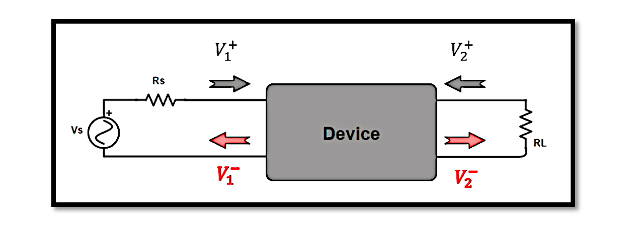
Imagine a two-port network with inputs labeled V1+ and V1–, and outputs labeled V2+ and V2–. When a signal is applied to the input port, it splits into two components: the incident wave, represented by V1+, and the reflected wave, represented by V1–. Similarly, at the output port, we have V2+ and V2–, indicating incident and reflected waves respectively.
Understanding S-Parameters Equations
The relationship between incident and reflected waves at each port is described by a set of equations:

These equations relate the incident (a1,a2) and reflected (b1,b2) waves at the input and output ports through the S-parameters (S11,S12,S21,S22).

S11: Input Matching Accuracy
The parameter S11 represents the ratio of the reflected wave V1– to the incident wave V1+ when V2+ is zero. In other words, it indicates how well the input is matched to the network. Mathematically,

A lower value of S11 signifies better input matching, ensuring maximum power transfer into the network.
S11, which is known as the input reflection coefficient. This parameter is crucial for understanding how well the input port of a two-port network is matched to its source impedance. S11 represents the ratio of the reflected wave V1– to the incident wave V1+ when the output port is terminated with a matched load (V2+=0). In practical terms, a low S11 value indicates effective input matching, meaning that most of the input signal is absorbed by the network rather than being reflected back to the source. Engineers often strive for low S11 values to minimize signal loss and optimize power transfer within the circuit.
S12: Reverse Isolation
Conversely, S12 reflects the ratio of the reflected wave V1– to the incident wave V2+ when V1+ is zero. This parameter quantifies the reverse isolation of the circuit, indicating how well the output is isolated from the input. Symbolically,

Higher values of S12 imply better isolation between input and output ports.
S22: Output Matching Accuracy
On the output side, S22 measures the accuracy of output matching. It represents the ratio of the reflected wave V2– to the incident wave V2+ when V1+ is zero. Mathematically,

Similar to S11, a lower value of S22 indicates better output matching, optimizing power transfer from the network.
S22, known as the output reflection coefficient. Similar to S11 but focusing on the output port, S22 represents the ratio of the reflected wave V2– to the incident wave V2+ when the input port is terminated with a matched load (V1+=0). A low S22 value indicates effective output matching, implying that most of the output signal is absorbed by the load rather than being reflected back into the network. Engineers aim for low S22 values to optimize power transfer and minimize signal distortion at the output port.
S21: Gain of the Circuit
S21, which represents the forward transmission coefficient and is essential for determining the gain of a circuit. Unlike the other S-parameters, S21 quantifies the ratio of the reflected wave V2– to the incident wave V1+ when V1+ is zero. In simpler terms, it indicates how much of the output signal is coupled back to the input network:

The S21 parameter essentially measures how effectively the circuit amplifies the input signal. A higher value of S21 suggests better amplification, indicating that a larger portion of the output signal is fed back into the input network. This parameter is crucial in amplifier design, where maximizing signal amplification is often a primary goal.
Understanding S-parameters is fundamental for designing and analyzing complex electrical networks. Engineers rely on these parameters to optimize circuit performance, ensuring efficient signal transmission and minimizing signal loss. By leveraging S-parameters effectively, engineers can design circuits with optimal gain characteristics, enabling them to meet the requirements of diverse applications in fields ranging from telecommunications to high-speed digital design.

Learn more about this topic by taking the complete course ‘Microwave Amplifier and Low Noise Amplifier (LNA) Design Theory and Principles online course – RAHRF526’. Watch the course videos for more detailed understanding. Also checkout other courses on RF system and IC design on https://rahsoft.com/courses/. Rahsoft also provides a certificate on Radio Frequency. All the courses offer step by step approach.


