Introduction RF losses in signal transmission play a pivotal role in the efficacy of factory testing and the integrity of RF circuits. Understanding these losses, their causes, and how to measure them is crucial for optimizing performance. Let’s delve into …
Introduction RF laboratory testing stands as a critical phase, a meticulous process that serves as the bedrock ensuring a product’s performance, functionality, and compliance before it ventures into mass production. This phase is where the intricate dance between innovation and …
Understanding Factory Testing Factory testing is the culminating stage in electronic device manufacturing. Also termed as final testing, this critical phase ensures the quality and functionality of products before they reach consumers. It’s the last line of defense against faulty …
Introduction Wireless technology has become an integral part of our daily lives, enabling seamless communication and connectivity. However, behind the scenes of every wireless device lies a crucial process known as Radio Frequency (RF) testing. But what exactly is RF …
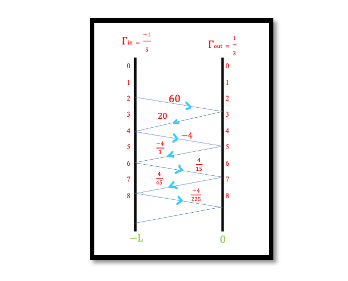
Introduction In the radio frequency (RF) engineering, the study of transmission lines stands as a fundamental pillar. These lines, vital for carrying signals over distances, exhibit intriguing responses to various input signals like unit steps and pulses. Understanding these responses …
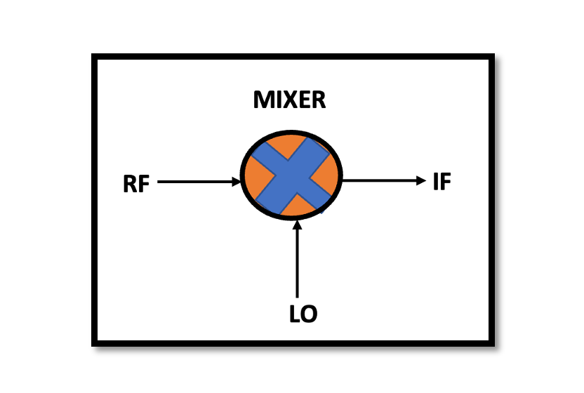
Introduction RF mixers’ ability to perform downconversion is critical in various RF systems, including communication, radar, and wireless applications. It enables the efficient handling of signals by reducing their frequency to levels suitable for subsequent processing stages. Additionally, it aids …
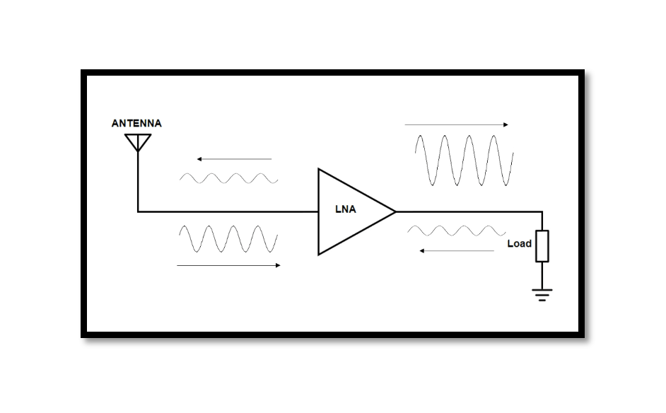
Introduction A Low Noise Amplifier (LNA) is a fundamental component within a receiver that plays a crucial role in boosting weak incoming signals while introducing minimal additional noise. It serves as the initial stage in the signal chain of a …
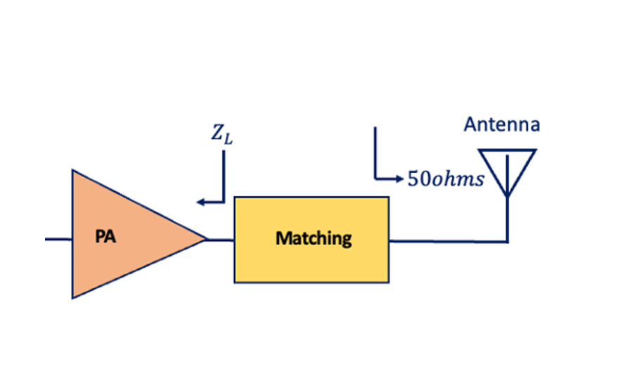
These devices form an integral part of modern electronics, serving to increase the power of a signal for various applications. Understanding their fundamentals is key to comprehending their significance in today’s technology-driven world. Power Amplifiers At its core, a power …
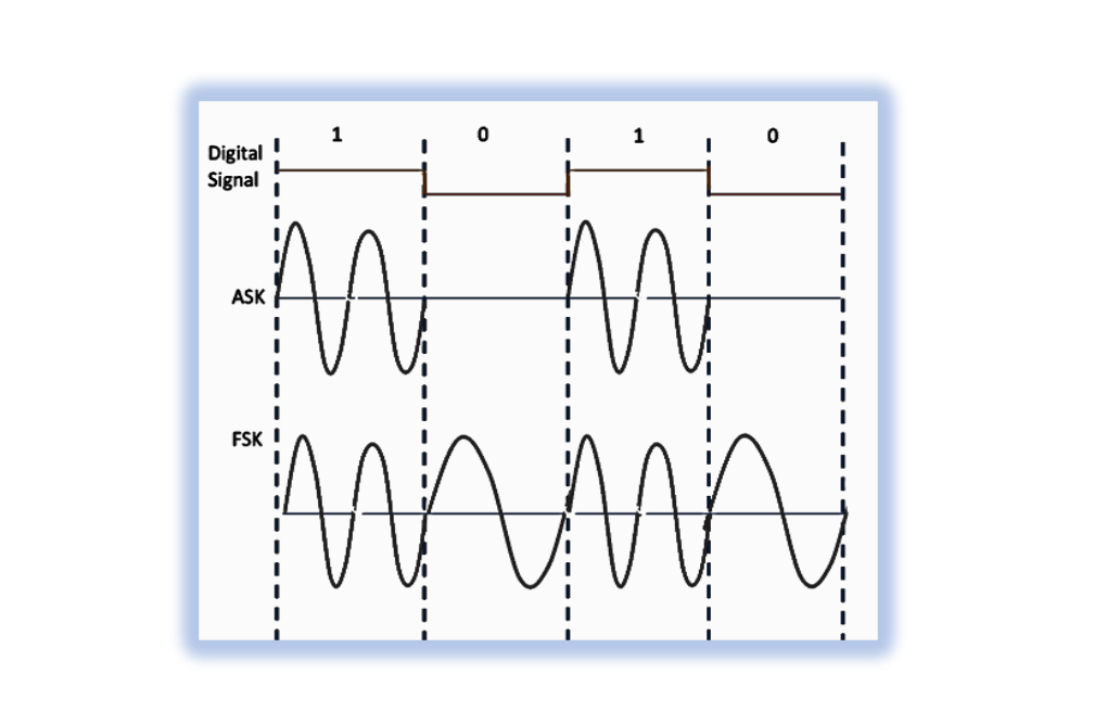
Analog Modulation Analog modulation, the precursor to digital modulation, revolutionized communication by enabling the transmission of voice, video, and other analog signals over vast distances. It involves modifying continuous signals, such as sound or video, to carry information across a …
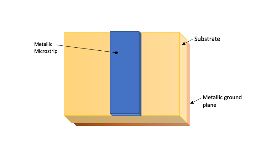
Introduction In the world of high-frequency circuits, microstrip lines stand as an integral element. These structures, consisting of a conductor on a dielectric substrate, play a pivotal role in modern electronic systems. Understanding their design, characteristics, and how to calculate …

