Heterodyne Receivers and its Components
Heterodyne Receiver
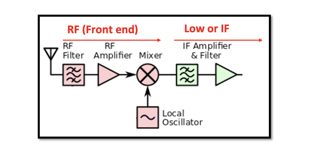
In a heterodyne receiver the received signal from an antenna is down converted from RF signal to intermediate frequency. Win is not equal to WLO. The basic structure of heterodyne receiver is shown below. There is an antenna connected to the receiver, we have RF filter for selecting our band and it is connected to the RF low noise amplifier and mixer for the down conversion. These blocks are called the front end of the receiver. At the end of the mixer we have intermediate frequency, after which additional amplification and filtering in IF part. These filters can be SAW filter or passive filter with active elements as it in high frequency.
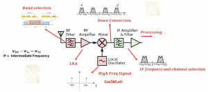
The components of heterodyne receivers includes antenna which is used on a filter to select desired band. Imagine that this is a GSM receiver so we can select the band of GSM with all channels. Then comes the RF amplifier which is basically a low noise amplifier, as the incoming signal is weak due to attenuation in the environment, the receiver RF signal is amplified. Mixer is used along with local oscillator for down conversion as we talked before in the section ‘Down conversion for RF Receivers’. Frequency of a given signal is shifted when it is multiplied with another sinusoidal signal called carrier wave. The local oscillator provides the carrier wave and both the input and carrier signals are mixed in a mixer and passed on to the low pass filter to attenuate the high frequency signal. In frequency domain the spectrum can be shown, where Wlo & -Wlo is carrier wave. The local oscillator produces carrier wave cos(wlot). So mixing these two signals we can show one of the channels where we get four kinds of signals after done conversion. An IF filter which can be a low pass filter is used to get rid of high frequency signals. Channel selection is also happening in this part of the receiver. Now we have been able to produce IF signal or shift over signal from RF to IF. The channel is sent for demodulation to get the data for example if it’s a digital modulation we have to demodulate to get our data. It is in IF and we need to bring it to baseband.

How does a heterodyne receiver cover a frequency band?
Method 1: There are two methods in order to down convert. In the first method the LO frequency is constant, and each RF channel is down converted to a different IF channel. Let’s say we have to down convert for all these given channels and our band is RF.
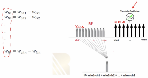
In this first method WLO is constant and we are not changing it. When all the channels within RF is mixed with WLO, they will be down converted to different kind of intermediate frequency as shown in the below figure. The channels within RF range from Wch1 to Wchn and in IF it ranges from WIF1 to WIFn. We can find WIF with down conversion as WIF1 = Wch1 – WLO. As it can be seen from the equations that WLO is always constant. We need a tuneable filter to choose each of these channels in IF. So we need a high Q band pass filter with a tuning part covering the range of IF. In this case an IF filter with variable center frequency to choose desired channel will work.
Method 2: In the second method the LO frequency is variable, so that all the RF channels within the band are translated to a single value.
Each channel within RF receives different WLO ranging from WLO1 to WLOn. We reach to the equation with same WIF as shown in the figure below, so all will be translated to a single IF value. We will have only one part for this channel. Therefore, in this method by changing WLO, different RF signals will be down converted to the same IF.
This method is challenging as sometimes designing a tuneable oscillator is difficult. Sometimes it is preferred to have tuneable filters rather than tuneable oscillator because tuneable oscillator is working in RF frequency and sometimes it’s hard to tune but the filter is IF filter and it’s easy to design, not in high frequency and can be tuned in wider range.


