Image rejection in Heterodyne Receiver
High-side injection: We have a channel, and to do down conversion, this channel is mixed with a local oscillator. There are two options to do this: first, we choose the frequency of the local oscillator (wLO) above the desired channel; this is called high-side injection. As shown in the figure below, when wLO is higher than the channel whose center frequency is w1 in the high-side injection. So, in this case, we can say that WIF = WLO-W1. When we say high and low sides, it refers to the frequency of the local oscillator.

Low-side injection: When the frequency of the local oscillator is selected below the desired channel in down conversion. As shown in the below figure. In both these cases, the difference between the channel’s center frequency and the local oscillator’s frequency is equal to wIF. So, in this case, we can say that WIF = W1-WLO.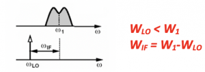
Image problem in a heterodyne receiver
The image problem is considered as one of the major drawbacks or problems with the heterodyne receiver.
What is an image signal?
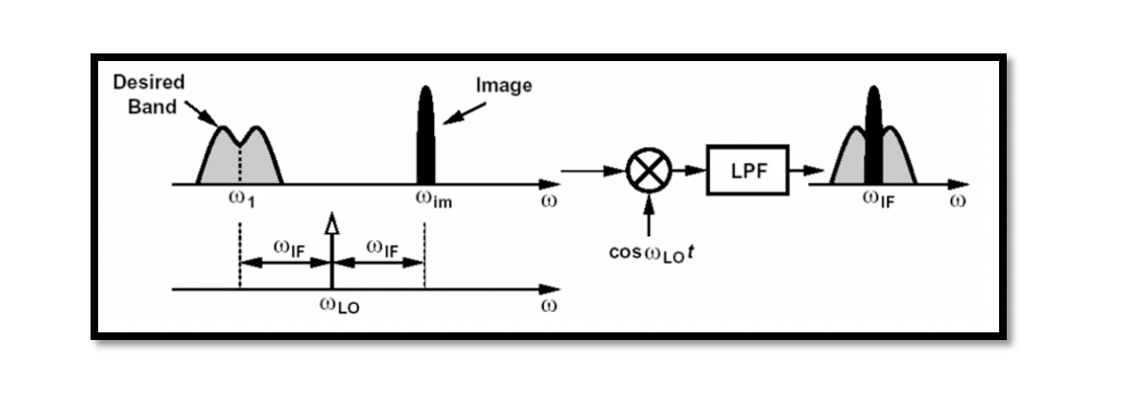
The image signal is generated when lots of users in other standards, for example, Bluetooth, GSM, WIFI, etc., transmit undesirable signals that act as interferers. So the different signals that are in the spectrum are considered undesirable and are called image signals.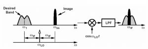
In the down-conversion process, we need the frequency of the local oscillator at a distance of wIF away from the center frequency of the desired channel. Still, it is also away from some other signal called the image signal with frequency wim.
During down conversion, the image signal comes on top of the desired band. So when we down convert, we have a copy of the image on top of our desired signal as the image signal also gets down-converted during the whole process. So in simple words, any signal that is at a distance of wIF from wLO is called an image. After down-conversion, both these signals will be translated to the same channel.
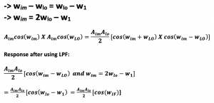
These equation shows the result when the image signal and local oscillator signal are mixed. We get two kinds of frequencies. Using a low pass filter will attenuate the first signal (cos wim + wLO); however, the other signal (cos wim – wLO) is equal to wIF, which will be translated to the desired band and corrupt and block the channel. A filter can be used to get rid of this image signal, which is called an image reject filter.
Effect of image for different LO frequencies
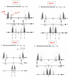
Case 1: In this case 1, we can see that wLO is less than w1, which is a low-side injection. So, in this case, after down-conversion, there is no problem with the image. The position of the image depends on wLO.
Case 2: In this case 2, we move wLO in between these two frequencies (-w2 & -w1, however, this case also doesn’t have any problem except that a high Q filter is required to filter the channel as the image is very close to the desired channel post down conversion.
Case 3: Now this case 3 is the main problem where wLO is exactly between the image and the channel. So post the down-conversion, the image will be directly translated inside the desired band. This is a high-side injection as wLO is higher than w1.
Case 4: In case 4, wLO is higher than -w2, and this is a high-side injection for both image and the channel. This case won’t be a problem as the image does not interfere with the channel after down-conversion. After analyzing all 4 cases, we can say that the only case that causes the problem is case 3, where the frequency of the local oscillator is equal to the center frequency of the desired channel.

Learn more about this topic by taking the complete course ‘RF System Design of Receivers, Transmitters & Transceivers – RAHRF409’.
Watch the course videos for more detailed understanding. Also checkout other courses on RF system and IC design on https://rahsoft.com/courses/.
Rahsoft also provides a certificate on Radio Frequency. All the courses offer step by step approach.


