Dual Conversion in Heterodyne Receiver
Dual Conversion
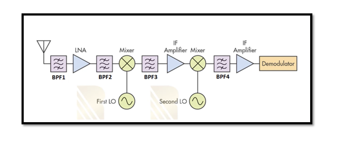
As discussed in the previous section, ‘Image Rejection vs Channel Selection’, there is a constant trade-off between the two. There is efficient filtering in low wIF, but the image rejection is insufficient, and in high wIF, the Image rejection is better, but we will have a problem in channel selection. So in order to solve this problem, the heterodyne receivers can be extended to accommodate multiple down-conversions. So, for example, there can be two stages of mixers and two IF.
First IF: At the first stage, when we are trying to choose high IF for maximizing the image rejection, so wIF1= wLO1 – win (high-side injection), so the image will be far away from the channel, and with designing a proper bandpass filter, the image signal can be completely attenuated.
Second IF: At the second stage, we will have low IF, so wLO2 – wIF1 = wIF2. Here, wIF1 is the result of the first mixer, and so we will get wIF2 which is a lower value allowing us to have effective channel selection. So this down-conversion takes place in order to translate channel to lower IF for designing high Q filters and maximizing the channel selection.
Step-by-step process of Dual Conversion in a Heterodyne Receiver

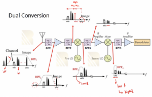
First, we have signals from the antenna this includes interferers around the desired channel as well as interferers outside the band, and there is an image signal close to our channel. This filter has sharp attenuation at a lower frequency than the high-frequency side, as seen in the below figure; hence, using this filter BFP1, the interferers at a lower frequency can be attenuated, but the image signal cannot be attenuated completely at this point. Therefore, we have a second filter BPF2 after the LNA, which is the image reject filter. So the image signal is attenuated at this stage. Until the first mixer wIF is high, which means the distance between win and wLO is quite high WIF1 = WLO1 – Win.
To select the desired channel and get rid of the interferers within the channel, the second mixer and filters will be used. After the first mixer, we have interferers around the channel, as shown in the figure. We are so using the BPF3, which is in IF we can design a low Q filter that will attenuate the interferer to some extent. So Channel is now downconverted to wIF1. There is an IF amplifier after BPF3, now the interferers are a little bit attenuated but not that much because the bandpass filtered tree is designed in IF1 and has low Q, therefore use the second mixer where the channel is downconverted to wIF2, and as IF2 is low we can design a high Q filter BPF4. So now, after filtering, we get our desired channel without unwanted interferers. After that, with additional amplification, the signal is sent for demodulation.
In summary a dual conversion heterodyne receiver has incoming signals with image and other bands which will be attenuated in BPF1. The BPF2 is the image rejection filter. Both BPF1 & BPF2 are kind of identical filters however, two attenuation levels are required in order to be sure that the image will be attenuated enough. The first mixer is designed for high IF to reject the image. Now we can go to wIF1 and then there is another filter BPF3 in order to attenuate the interferer which is not enough and finally after down converting by second mixer the BPF4 is used in low Q for desired channel selection and totally getting rid of interferers.


