Features of Dual Conversion Receiver
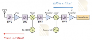
In cascaded system the Noise Figure (NF) is important in first blocks and it is vice versa in case of IP3, where the NF of last blocks matters more. So in a dual conversion receiver the noise figure of bandpass filter one (BPF1), the LNA and BPF2 are really important but we don’t care about other blocks as the noise figure of these blocks will be divided by the gain of mixer and LNA. Therefore the input referred noise contribution of these blocks is minor.
In case of IP3 the IF amplifier at the end of the receiver has to be more linear than the LNA at the beginning of the receiver because linearity is more important when it comes to end of the cascaded systems. Therefore when we compare the three amplifiers in the below diagram, IF amplifier at the end should be more linear than the IF amplifier in the middle, which in turn has to be more linear than the LNA. Similarly the BPF1 should have really less noise and less loss as well as the BPF2 which is a image reject filter. As discussed in previous section ‘Image Signal in Heterodyne Receiver’ this image rejects filter is placed after the LNA. The reason for putting it after LNA is, filter contributes to noise, and if placed before LNA, it will add noise which will again get amplified, contributing to the receiver’s noise figure. So noise of this filter will be divided by gain of the LNA.
Mixing Spurs
One of the most important issues in dual conversion receiver is mixing spurs. It is always assumed that our local oscillator produces fundamental frequency of ‘A cosWLOt’ however, this is not true in real world as we face a problem which is the mixers producing harmonics. So we will have additional components called harmonics (2WLOt, 3 WLOt…). Assuming we have two mixers doing the down-conversion. The first mixer that is the RF mixer will produce components at ‘Win +/- mWLO1’
The second mixer in the second down-conversion produces components at ‘Win +/- mWLO1 +\- nWLO2’. So at the output instead of having one frequency we will have different kinds of frequencies caused by the harmonics of mixers.
Imagine if we have an interferer at the frequency of Wint and if Wint +/- mWLO1 +\- nWLO2 = Wsig – mWLO1 – nWLO2 then this interferer will be downconverted to the channel’s frequency and translation of such a signal will corrupt the channel.
Example to understand Mixing Spurs
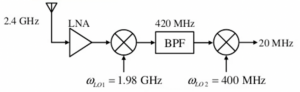
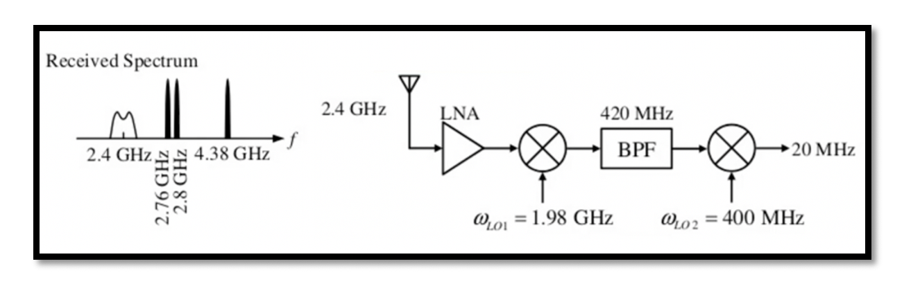
The antenna receives the channel with the center frequency of 2.4GHz. This received channel is going to be mixed with local oscillator frequency of 1.98 GHz and will go through first down-conversion for WIF1 which is 2.4 – 1.98 and the second down conversion when mixed with 400 MHz, as you see it’s a very low frequency so we have 420 MHz here then 420 – 400 we will have 20 MHz which is the center frequency of our channel now.
Let’s see what the problem with mixing spur is here. If this mixer here has second harmonic of 800 MHz, so we need the kind of signal we need to mix for 800 MHz and get output as get 20 MHz. Imagine that we have 820 MHz interferer signal and it reached here as it has a very high amplitude. The band pass filter and other filters have attenuated this signal but it’s not enough. So 820 MHz- 800MHz that is the second harmonic of this mixer will produce 20 MHz and it will block our signal.
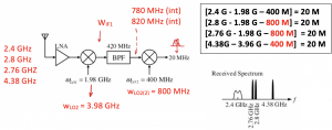 Therefore, going backwards 820MHz will be mixed by 1.98GHz then we will have 2.8GHz of interferer frequency. The other cases are it can be less than 800MHz, like 780MHz. When we mix 780MHz with 800MHz we will get 20MHz again. Working backwards we will get the interferer frequency when mixed with 1.98GHz of local oscillator frequency we get the interferer frequency as 2.76GHz. The last case is when we have second harmonic of first mixer that is 3.96GHz so we want to have 4.38GHz interferer and mixing this with 3.96GHz we will have 420 MHz. Then 420MHz mixed with second mixer 400MHz giving 20MHz output.
We have three mixing spurs in this system and if these signals are not removed completely, they will be translated inside our channel in IF. So if translated all these to IF we will have channel in IF which is 20MHz and these interferers will be included within our channel corrupting it. Though these interferers will not have high amplitude due to the filters within the system.

Learn more about this topic by taking the complete course ‘RF System Design of Receivers, Transmitters & Transceivers – RAHRF409’.
Watch the course videos for more detailed understanding. Also checkout other courses on RF system and IC design on https://rahsoft.com/courses/.
Rahsoft also provides a certificate on Radio Frequency. All the courses offer step by step approach.
You may also like
Understanding Quadrature Amplitude Modulation (QAM) and Its Applications