What is Frequency Shift Keying (FSK) Receiver
What is Digital modulation?
Digital modulation is used for mapping the binary information sequence over an analog channel (bandpass modulation) appropriate for transmission into the communication channel. This enables us to convey a large amount of information. In addition, Digital signals can be handled with higher security and are readily available. The developers of digital communication systems faced constraints like permissible power, available bandwidth, and the system’s noise level. The move to digital modulation provides more information capacity, higher data security, compatibility with digital data services, better quality communication, and quicker system availability. Digital modulation is also used in broadcast systems & cable TV. Digital modulation has more capacity to convey a large amount of data.
Depending on which parameter of the carrier signal is varied following the digital message signal. There are three primary variants of digital modulation called Amplitude Shift Keying (ASK), Frequency Shift Keying (FSK), and Phase Shift Keying (PSK).
The carrier signal has three degrees of freedom that can be modulated, namely, amplitude, frequency, and phase. Modulation schemes can be considered concerning one or more of these degrees of freedom. For example, if we consider just one degree of freedom of the sinusoidal carrier, we can modulate the digital data in one of the following ways. These are the primary variants of digital modulation:
- Modulating the amplitude of the carrier wave, known as Amplitude Shift Keying (ASK).
- Modulating the frequency of the carrier wave, known as Frequency Shift Keying (FSK).
- Modulating the phase of the carrier wave, known as Phase Shift Keying (PSK).
What is Frequency Shift Keying (FSK) modulation?
- The information is transmitted through discrete frequency changes of the carrier signal.
- The signal’s amplitude is not so important, making the FSK signal robust against amplitude distortion and attenuation, for example: during wireless channel transmission.
- For optimal reception schemes, it has been proven that the FSK signals should be orthogonal. Therefore, GSM cellular network uses FSK with orthogonal frequencies.
Example:
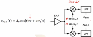
FSK direct conversion receiver. xFSK (t) = A0 cos [(wc + aw1)t], where a = +/-1.
xFSK (t) is the modulated signal.

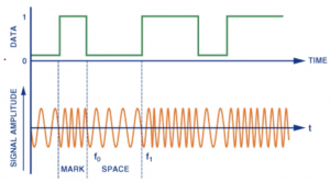
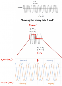
We have digital serial data that is binary digits 0 and 1 in the below figure. So how can we modulate this data? When the signal is 0 it means we are sending the carrier with a frequency of wc – w1. This w1 is really small and has a lower value compared to wc. When the signal is 1, it means we are changing the frequency of carrier wave to wc + w1. Frequencies are denoted as f1 and f2 where f1<f2. F1 represent the low or zero binary data and f2 represents the high data or 1.


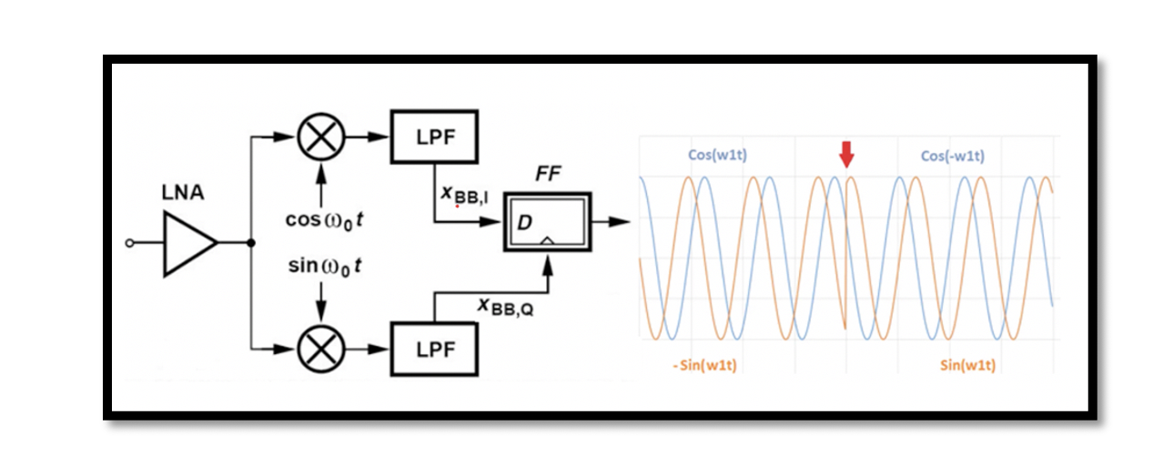
The modulated data is fed to LNA in the receiver for amplification, after that there is direct conversion receiver where we have zero IF. In direct conversion receiver we convert RF directly to zero IF. The down conversion has only one step in this receiver type, from RF to zero IF. After the quadrature down conversion using mixers, one fed with a cosine wave (cos w0t) and the other with sine wave (sin w0t), we will get baseband in-phase XBB, I(t), and quadrature XBB, Q(t) after doing filtering. Now we are setting w0=wc, that is the carrier frequency and let the amplitude be B.


How can we down convert and modulate our signal?

Assume that we have this kind of output as shown in the figure. The in-phase and quadrature part can be shown in this figure. The red arrow shows the point of change of frequency. When a= -1 cosine doesn’t change, cos(w1t) = cos(-w1t). The sine wave polarity changes. A filp-flop can be used for demodulation in the structure. The baseband signals XBB, I(t) is fed to the data flip flop and we have a clock, so this clock is sensitive to falling edge and XBB, Q(t) is our clock. The below figure shows the falling edge. D flip flop picks the data in falling or rising edge and it depends on the clock. The blue wave is the data and orange wave is the XBB, Q(t). At the end we get the pulse. The data is demodulated using this filp-flop block. This structure is used for FSK where we can get the data, down convert it and demodulate the data using flip-flop.


