Can High Pass Filter be used in Solving DC offset in Homodyne Receiver?
How can the DC offset be removed? How to solve the problem of DC offset in direct conversion receiver?
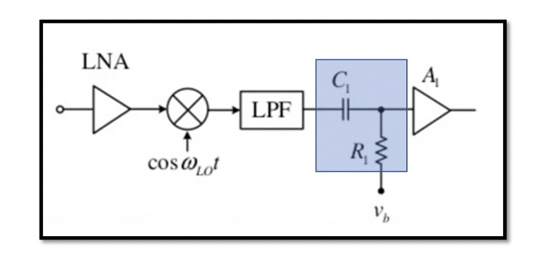
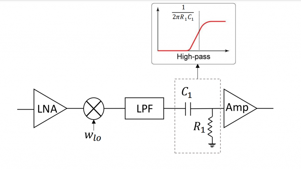
The previous section we discussed about the drawback of homodyne receiver which is DC offset. This DC offset is due to the local oscillator leakage in the base band. The high pass filter can be used. DC means zero frequency so we can remove it with using high pass filter. As shown in the below figure a high pass filter can be designed using a capacitor C1 and resistor R1. The high pass filter has a response as shown below for frequency vs amplitude. C1 and R1 acts as high pass filter and the corner frequency equal (2πR1C1)-1.
However, there is a drawback or problem in using this method for removing DC offset.

What are the drawbacks of using high pass filter for solving DC offset?
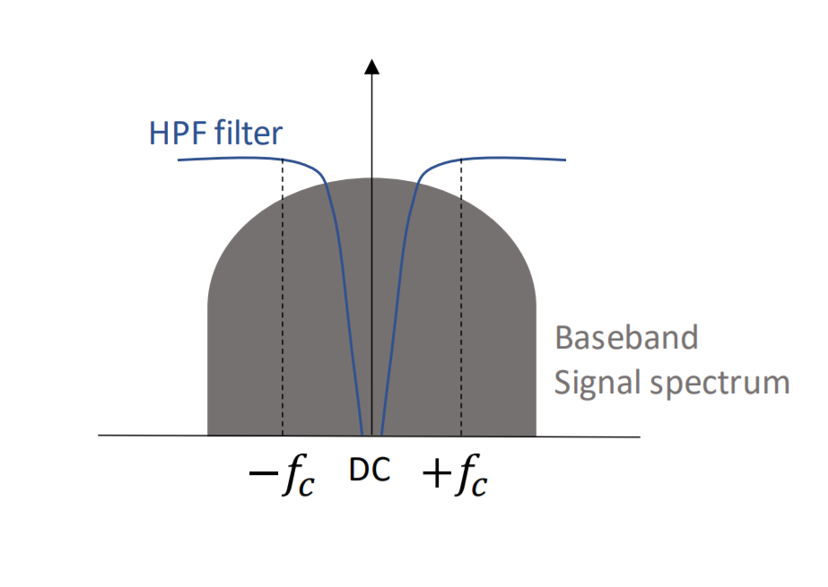
- Such a filter also removes the fraction of signals spectrum near zero frequency.

If we have a channel like shown in the above figure and we have information close to the zero frequency, so using a high pass filter which is not sharp will attenuate the data near the zero frequency. The DC is near the zero frequency and there is information close to the DC frequency, so when such a filter is used it removes the fraction of signals spectrum near zero frequency.
There are some applications where this method of using high pass filter to remove DC offset can be used for example the high index FSK modulation.
For small index modulation we face the problem of information loss as there is information close to zero frequency, however, as shown in the above figure for high index modulation, we see the is no important modulated data near zero frequency during down conversion, therefore high index FSK modulation can use a high pass filter to remove the DC offset.

- The high pass filter has slow response to the transient inputs.
- It has long time constant.
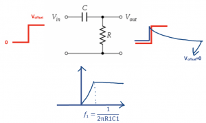
The high pass filter has slow response to the transient inputs. So let’s take an example to understand this problem, so imagine that we have a pulse input for this below circuit. It changed from zero to the offset DC value and we want to eliminate this offset.
The output response for this circuit is shown where at this point the offset voltage will be cancelled (Voffset = 0). The high pass filter is slow it takes a long time, we know the settling time is approximately equal to four times the time constant but we have longer time constant for the circuit. If we see the spectrum, the response of high pass filter where the corner frequency (2πR1C1)-1 is close to zero frequency because we want to remove the DC value here so it means that f1 is low and then we can conclude that R1C1 is high which proves that the time constant is long. So it takes time for the circuit to eliminate the offset. Problem of our circuit is it takes time for the circuit to eliminate the offset and we want to eliminate the DC offset very fast.
This circuit fails to block the offset if it changes suddenly. This pulse is showing the sudden change in offset voltage and that’s the problem so what is the source of this sudden change.
How sudden change occurs in offset?
- The offset depends on our circuit for example let’s say we are changing the LO frequency, so the LO frequency is switched to another channel and it changes the leakage.
As discussed in previous we said that the RF signal is combined with the local oscillator voltage with coefficient k, it means that the voltage doesn’t have same amplitude as it paths through different ways, however, the frequency (wLO) remains the same. coefficient k with frequency and with gain. So our offset is changing frequently.
- The gain of LNA is switched to different values. If we have tunable LNA and we are changing the gain of LNA it means we are changing the reverse isolation so again we are changing the coefficient k, k depends on reverse isolation of LNA.
Therefore we have a sudden change for offset and this given circuit where we used C1 & R1 is slow and it won’t be able to follow and eliminate the offset voltage.

Learn more about this topic by taking the complete course ‘RF System Design of Receivers, Transmitters & Transceivers – RAHRF409’.
Watch the course videos for more detailed understanding. Also checkout other courses on RF system and IC design on https://rahsoft.com/courses/.
Rahsoft also provides a certificate on Radio Frequency. All the courses offer step by step approach.


