Solving Oscillator Pulling in Transmitters
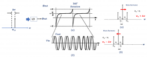
In the previous blog, we discussed about what is Oscillator Pulling. Oscillator Pulling can be explained from another point of view. If a sinusoid at the frequency of w1=wLO+∆w is injected into the oscillator operating at the frequency of wLO the output phase of the oscillator will be modulated periodically.
The phase of the output signal will change periodically as shown in the diagram below. It will experience 360˚ rotation meaning it’s sometimes -180˚ and sometimes 180 ˚. The phase changes all the time, it increases and decreases so if we see the output spectrum, we can see injected frequency (winj) higher than wo which means that the center frequency so means the injected frequency is wo+∆w. The main harmonic is getting far from wo, getting pulled to the right side and vice versa if we have injected signal at a frequency less than the center frequency the signal would be pulled to the left side so it will be wo-∆w and now it’s pulling to the left side.
How to solve Oscillator Pulling?
In this blog, we will discuss about the possible solutions to solve oscillator pulling.
wLO is chosen far from wc
- Injection pulling is reduced
- Frequency divider easily provides quadrature carriers
- Drawback: PA non-linearity produces harmonics which does not completely remove injection pulling.
The frequency of the Local Oscillator (wLO) is selected far from the center frequency of the channel (wc). If the frequency of the local oscillator is equal to the center frequency of the channel a signal which has a frequency close to wc can be injected to the oscillator and pull the frequency.
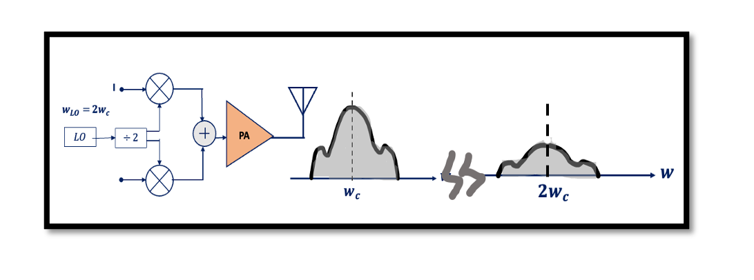
To get rid of this problem we try to create different frequencies. In this scenario, we are operating the local oscillator at 2wc (double the frequency) as shown in the diagram below. But we also want to have the same carrier frequency and implementing this is very simple. We design a local oscillator to operate at 2wc but we want wc as our carrier. For that, a divider is added to the structure. As we already that using a divider will produce quadrature carriers; cosine wc and sine wc. So injection pulling is reduced. Imagine if there is a signal next to wc and if it is getting injected into the local oscillator it will be around wc but our local oscillator is operating at 2wc hence there will be no effect.
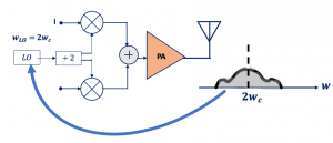
The frequency divider provides quadrature carriers but we are not eliminating the problem of oscillator pulling completely. The power amplifier has non-linearity and will produce the second and third harmonics at the output so again we will have something like this as shown in the output of the below diagram because of PA non-linearity:
The signal can be injected from this channel to the local oscillator, but if the signal that’s injected has low amplitude then it won’t have much effect on the local oscillator. As we can see the channel has a low amplitude.
The structure has a drawback in terms of the speed requirement of the divider. The divider is operating at wc, it’s challenging to design. Other transmitter structures also have some drawbacks so saying it might be worth focusing on designing a high-speed divider that can make a perfect transmitter. There are other methods to solve oscillator pulling without a high-speed divider that we will discuss in this blog.


