Introduction to Heterodyne Transmitter
Heterodyne Transmitter
Heterodyne Transmitter is a two-step upconversion, just like heterodyne receiver which is a two-step downconversion. Read about the heterodyne receiver. This structure involves two steps of mixing and there is no oscillator pulling problem, however, just like other structures, there are drawbacks in this kind of transmitter as well that we will discuss later.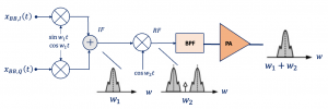
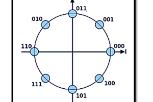
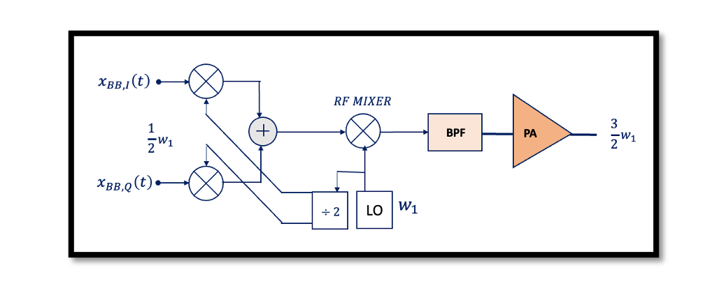
Heterodyne Transmitters are used to solve the injection-pulling problem. Read about injection pulling. We are upconverting the baseband data to IF as shown in the structure below. In the below structure of the Heterodyne receiver, we are using quadrature mixing assuming we have GMSK modulation in this structure. At the end of the first mixing, we have IF and then there is another mixer in order to upconvert IF to RF, so at the output we have RF.
We have shown the output channels along with the sidebands at the end of the second mixing. At the output we have two channels and using a band pass filter we are removing one of these channels to have frequency w1+w2 at the output where w1 is IF and w2 is RF and w1<w2. The band pass filter is used because these frequencies are actually far from each other so it’s possible to filter them and we will have w2 due to nonlinearity which we will discuss. If the system is perfect, we don’t have w2 in this spectrum. So this describes the whole operation of a heterodyne transmitter.
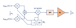
In the heterodyne structure here we are using the same Local Oscillator (LO) for both w1 and w2 using a divider as shown above. So at the output, we have the combination of these two frequencies (3w1/2). Let’s talk about the drawbacks of this transmitter structure.
Drawbacks of Heterodyne Transmitter
- DC Offset
This structure has a drawback. The first drawback is DC offset at the baseband. What is DC offset? DC offset is coming from local oscillator leakage. The local oscillator leakage problem causes a large DC offset in the baseband and saturates the baseband circuits. There are two total DC offsets; Vos1 and Vos2, they are two DC offsets referred to as the input port of the mixer, we can show this using the diagram below: This unwanted signal is due to the DC offset at the input of the RF mixer means the second mixer.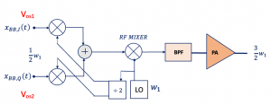
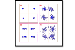
The analog baseband circuit producing the quadrature signals in the transmitter exhibits DC offset. At the output, we have the term with GMSK and two unwanted signals, which is one of the problems and we can show the measure which is called the relative carrier leakage. Below we have shown the IF and RF output channels. 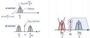
We have an unwanted component in the middle of the channel shown by an arrow in the IF output. After mixing the IF output with the second mixer we get the RF output with side bands and components and also this unwanted component is represented by an arrow at w1 which is coming from the DC offset at the input of the RF mixer. Using a band pass filter we can get rid of the side channel but the unwanted component is still present because it’s very close to the desired channel.

Learn more about this topic by taking the complete course ‘RF System Design of Receivers, Transmitters & Transceivers – RAHRF409’. Watch the course videos for more detailed understanding. Also checkout other courses on RF system and IC design on https://rahsoft.com/courses/. Rahsoft also provides a certificate on Radio Frequency. All the courses offer step by step approach.
You may also like
Understanding Quadrature Amplitude Modulation (QAM) and Its Applications